So I’ve been think of what setup is best for me to use in my experiment. The science paper uses a folded cavity. But this is costly and complex to align. To make sure I am thinking straight, I just simulated the cavity setup I will probably opt for in order to reduce cost and complexity. Also will make the laser system far more compact too.
That is only a loose simulation. The cavity would be tighter than that in reality. Something else to bare in mind, is this cavity would run at ~56-57 degrees off the PMMA axis of rotation to utilise the brewster angle. That axis is also the most translucent, increasing its damage threshold.
What you have is a pump beam down in the bottom right of the image. This is focused on the PMMA at as tight of an angle as possible to result in more photons being captured by the laser cavity. However it cannot be to tight in order to not interfere with the cavity itself. The pump is single pass. The result of this input beam would produce intense fluorescence and output light like a point source. If the photons that are emitted are travelling in the direction of either of the two mirrors they will be captured and reflected within a hemispherical setup. The photons will then start to initiate lasing action by knocking other electrons down and emitting more photons.
I chose a hemispherical cavity to reduce the cost of needing a specialist concave output coupler. This would likely put the optic in the $$$$'s alone. Concave high reflectors are not as expensive or as specialist. Also the cavity length can be drastically reduced. Without a need for a fold, you don’t need to buy further optics or need to have hassle aligning the cavity. Also a more compact cavity is more practical. To reduce cost further I could of opted for a planar high reflector. However you need some sort of focal region otherwise efficiency is limited only to those photons travelling in exactly the right direction. The efficiency may be so low that lasing may not be possible at all because the lasing threshold may become to high that the damage threshold will make it impossible. To reduce damage and dye bleaching, the acrylic must be fabricated into a disc which can be spun. This decreases the amount of time the same area of PMMA is exposed to the pump beam. Also as known with liquid cw dye systems. The dye has to be circulated. This is effectively the exact same principle only working with a solid medium. I might build a system that both rotates the disc, and moves it slowly horizontally like etching a CD.
I’ll share a view of my setup in more detail when I get a chance.
1 Like
I will kick in 500 dollars for the optics, when you are ready.
1 Like
Wow, thanks Chris. That is generous. I will be keeping this project as cheap as possible. For one, being a acrylic laser it feels like a DIY project anyway. The only thing is the mirrors of which I’m sticking to two only anyway. Output coupler and one concave high reflector. I’m still going through each spectrum atm.
OK, well, if it works out I will duplicate your work for my own 
1 Like
Of course. Still got to confirm, but I’m sure one sample worked well under 520nm of which you own high power of. I don’t own 520nm at high powers.
Probably the best plan of action, is for me to get a setup complete and test the laser that I most believe to work. If I can get that working then I will show you how to make your own so you can test pumping at 520nm. Obviously you also have a very high power 532nm in your collection.
One thing I would say Chris. This is experimental. I can’t guarantee I will get lasing action. There is good reason to believe I can however. So I don’t want you investing in this unless you are not minding having a chance of failure. The results however if we pulled it of would be outstanding progress for our hobby.
1 Like
I have changed this thread into a community project. As its gone more from talking about the research to now contributing our own.
@Laser_Project
I designed the cavity to be as compact and as practical as possible. I’ll write up the principles of the design so we can use it as research later if needed.
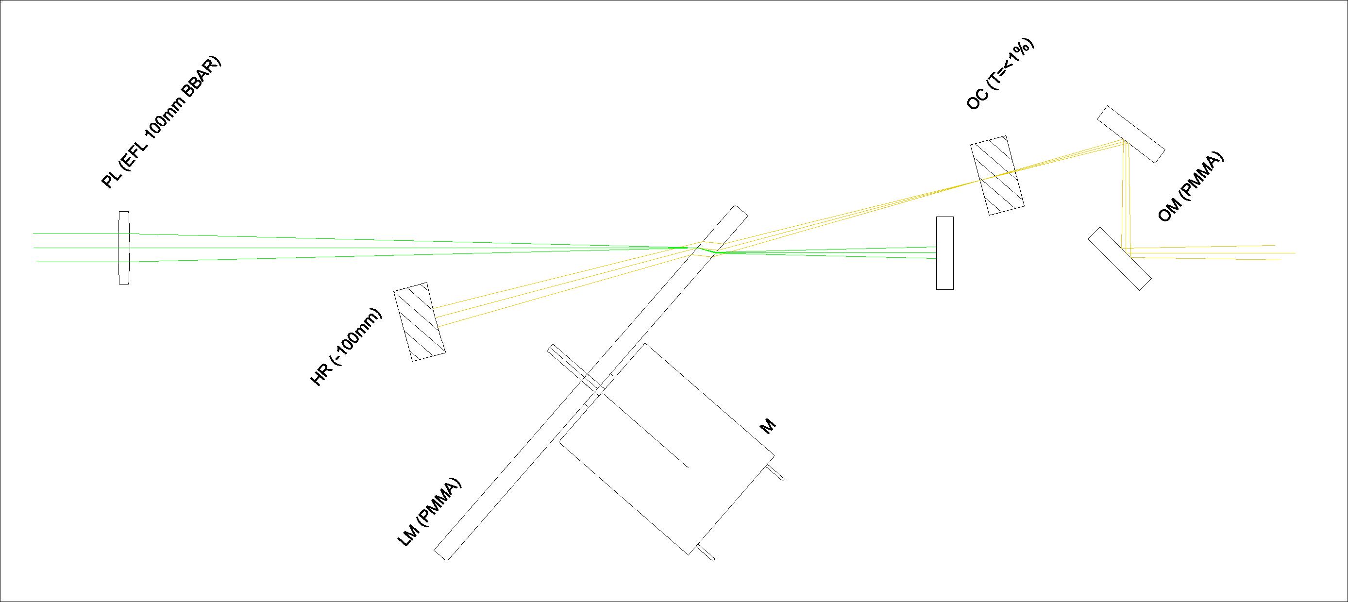
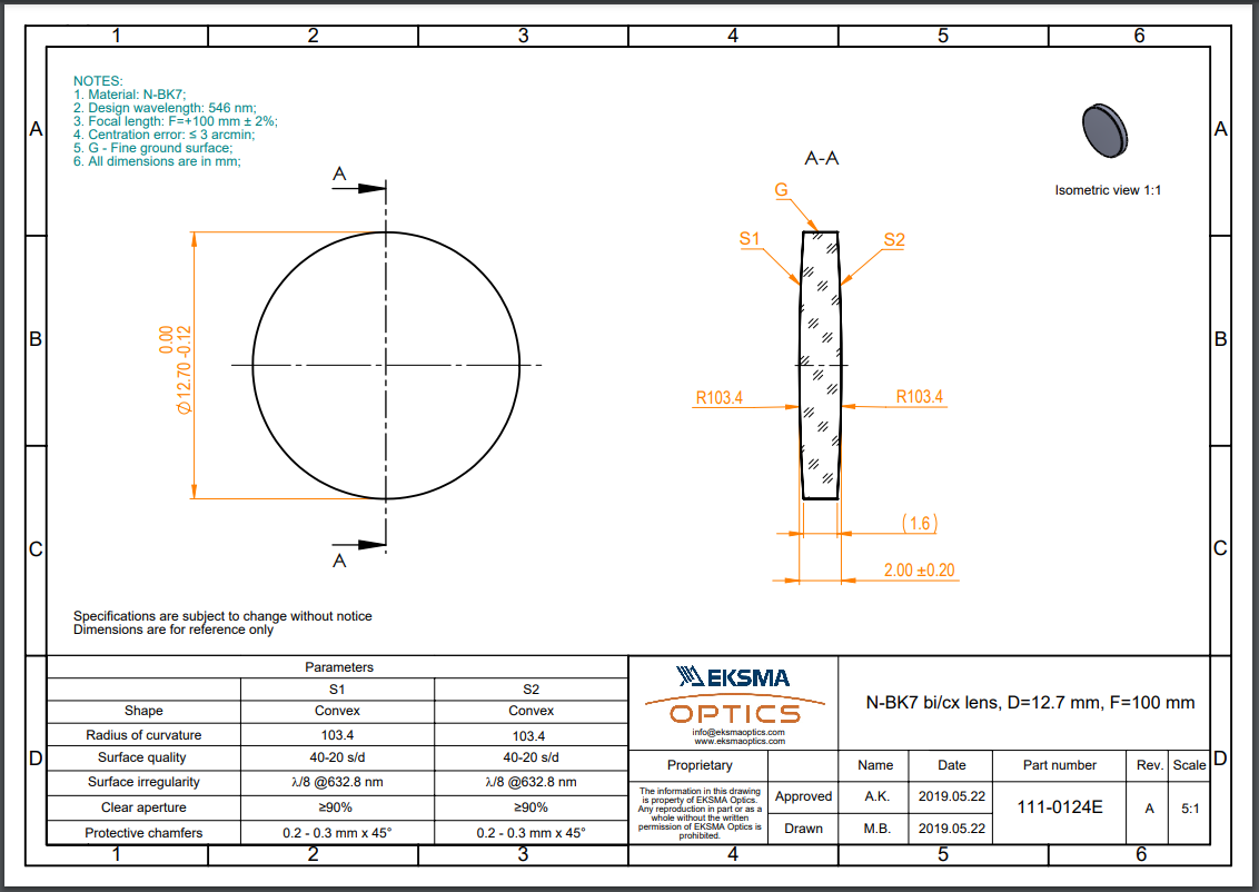
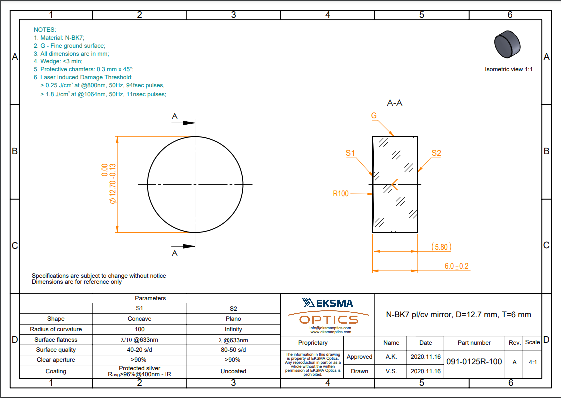
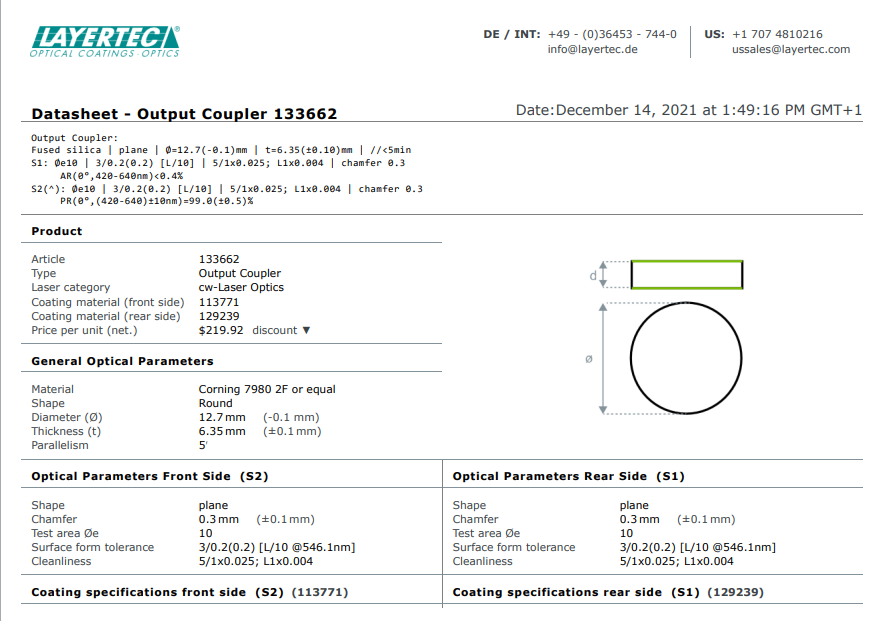
The pump beam is focused by a 12.7mm dia BK7 biconvex lens with a EFL of 100mm [PL](Fig 1). The lens will need to be BBAR coated to minimise back reflections into the pump source. The laser medium [LM] will consist of a 80mm dia 3mm fluorescent PMMA sample. This will be spun by a motor [M] at an angle of 34° to the lasing axis or 49° to the pump beam. The lasing axis corresponds to the Brewster angle of PMMA. (90°-56°=34°). The pump axis is tilted at 15° to the lasing axis. This is kept at a minimum without the pump beam interfering with the lasing cavity. Both lasing paths account for PMMA refraction as shown when looking closely at the laser medium [LM]. The laser cavity consists of a 12.7mm dia concave high reflector [HR] of -100mm curvature (Fig 2) and a 12.7mm dia BB T=<1% output coupler [OC] (Fig 3). The low transmittance will give exceptional gain to the medium reducing the lasing threshold however sacrificing some slope efficiency. The output coupler has is broadband (BB) therefore allowing the cavity to be reutilised for alternative PMMA laser mediums without a problem of additional cost and optics. The chosen cavity type is hemispherical meaning the lasing path is focused onto the high reflector. This has benefits of reducing cost and complexity within the system. Alternative methods have utilised folded spherical (concentric) cavities. Having a concave output coupler as well as a concave high reflector adds significant cost to the system. Folding the laser path also adds further complexity regarding the internal cavity where alignment is critical. Not to mention another optic and larger optical layout. The hemispherical setup greatly reduces alignment error and cavity size. Testing under optical simulations (Fig 4) I have opted for a 50/50 distribution for the laser medium [LM] and the OC and HR. Greater photon capture may be possible by having the HR closer to the laser medium. However photon intensity is greater nearer the OC. The perfect balance between the two is to opt for 50/50 distribution. This also keeps the spinning PMMA away from the fragile optics in case of mechanical failure. Lastly the output from the lasing cavity is folded by output mirrors [OM]. The purpose of these is to correct the output angle and beam positioning. These are non-critical as they are external to the laser cavity. They will also be DIY constructed using mirrored PMMA to reduce cost for essentially a feature meant for practicality and to favour aesthetics. The output beam can then be collimated using any stock convex lens.
(Fig 1 - Pump Lens [PL])
(Fig 1 - Coating)
(Fig 2 - High Reflector [HR])
(Fig 3 - Output Coupler [OC])
(Fig 4 - Optical Simulation)
1 Like
Nice work, let me know when ready to order optics.
1 Like
Will do. I want to run a test cavity first both simulated and physical minus the bought optics. Annoyingly I did a simulation today but it crashes before I could screenshot. Principal of the cavity worked out. I’ve cut myself a load of 80mm discs out of the fluorescent orange due to this being unknown and finite atm. I also cut myself a batch of some 12.7mm mirrors out of mirrored pmma. These will act as low cost high reflectors for non crucial parts of the optical path. I’ve broken up from work, so I’ve got time to get some more theory done before delving into making it. I will be testing and constructing mainly at work.
1 Like
@Laser_Project
So I have simulated my cavity again with higher precision, and have found best results using a ROC-50mm HR instead of the logical and original choice of ROC-100mm. The total cavity length is 97.98mm to be precise accounting for the refraction within the PMMA. I was presuming having a ROC-100mm HR would create the perfect hemispherical cavity if accounting for coherent photons. However I am trying to get gain out of the fluorescence which essentially acts as a point light source at both the front and rear surface of the PMMA. This makes those photons highly divergent and in need for a higher power HR. I got lucky that a stock mirror of equal cost is available. I do not have to make any changes to my optical setup however so my original drawing still stands with the change of HR. These are exactly the sort of unpredictable errors I want to capture early before you invest money into this. Ideally a concentric cavity would yield the best efficiency, but we simply cannot justify or afford it for this project. A hemispherical cavity is however achievable and verified by simulations.
I have been carefully considering all the things that will affect the outcome of this laser. The number one is alignment. I will have to spend a lot of time custom designing 3d printed translation stages, rotation stages, and kinematic mounts. That way I can have full control on where the mirrors point and their positioning. The second actually comes down to spinning the PMMA sample. The PMMA needs be spun true with no wobble. Wobble will alter the refractive path and affect the lasing process. Depending on the severity of the wobble this may not be significant as the hemispherical cavity will work with whatever photons are captured. But less wobble and more guarantee the capture will be higher and output will be more stable. The next, is we are working with PMMA samples with unknown dyes. These dyes may suffer degradation that we can’t account for, and the PMMA will have a low laser damage threshold. Less important considerations are manufacturing and processing defects in the PMMA. This will affect the output stability.
To keep cost down Chris, I will be checking my own stock of lenses to see if I have an appropriate fit. I won’t be getting you to order one AR coated unless absolutely needed. I simulated tilting the lens of axis slightly and it worked. So I can remove the risk of back reflection into the pump laser by offsetting the angle by 1-2° without any drastic change to the pump beam.
One question. These have the ability to tuneable. Do you want to try that, or let it lase its strongest natural line?
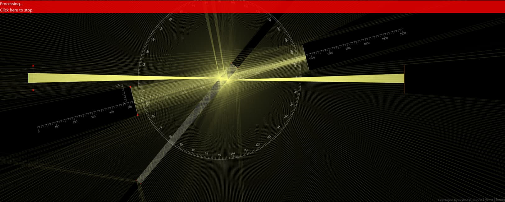
Simulations:
These simulations are accurate and to scale at 10:1 as the simulator doesn’t like small parts. All angles and optics are accurate as can be rendered without computer aided help.
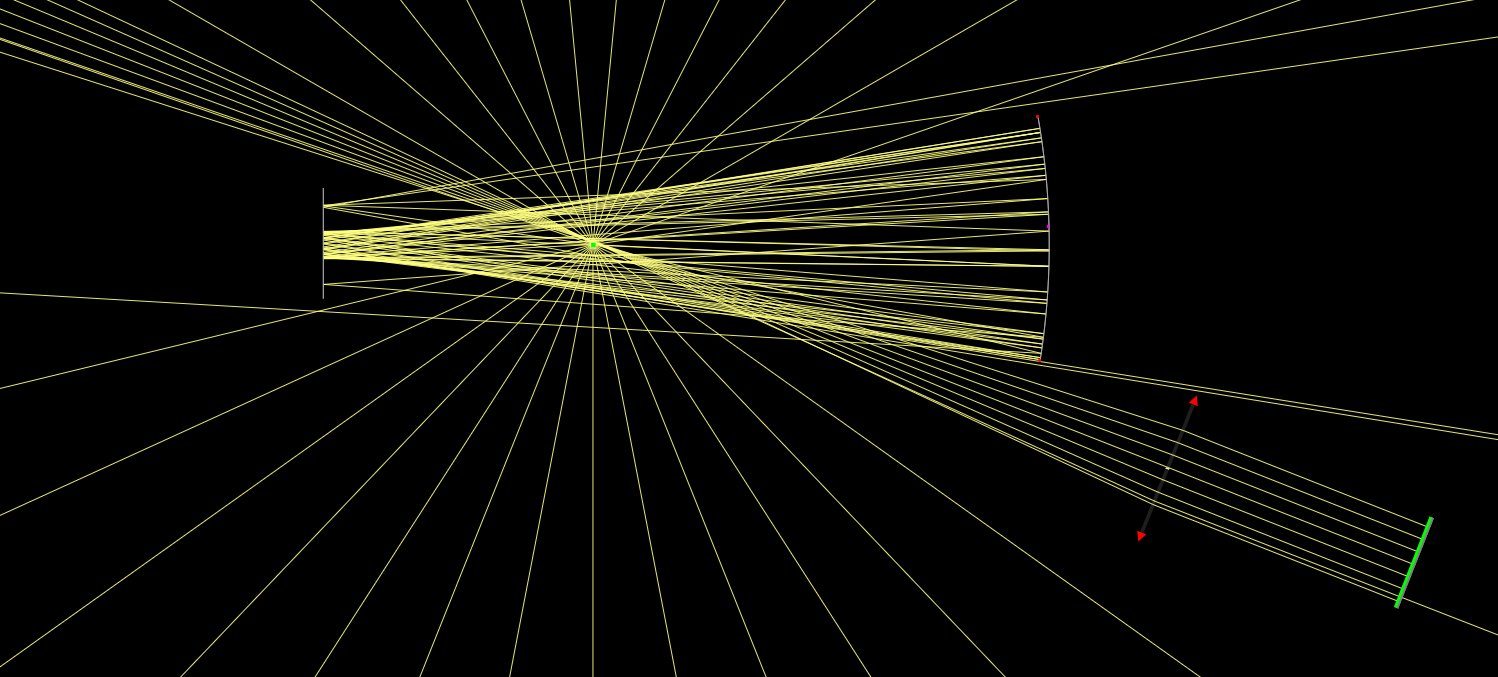
Low ray density view to show that the cavity is definitely working. The red processing bar shows there are continuous reflections being calculated.
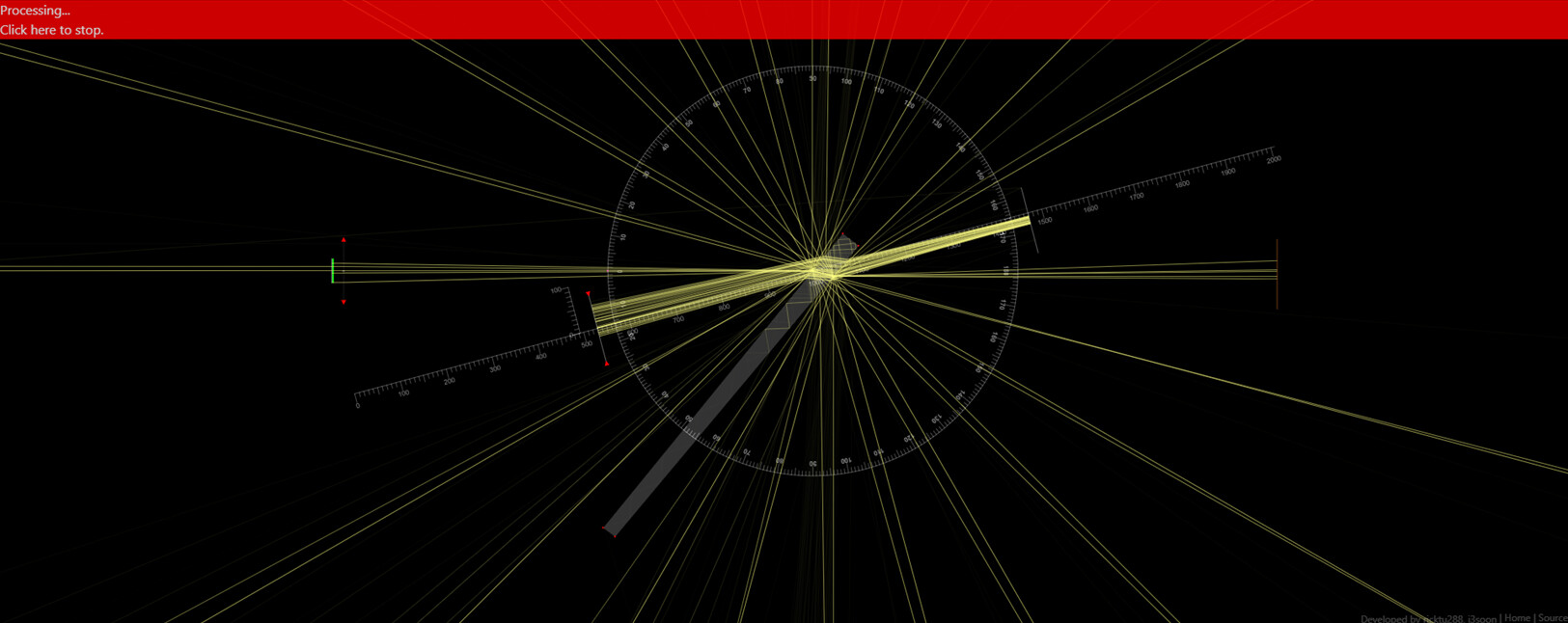
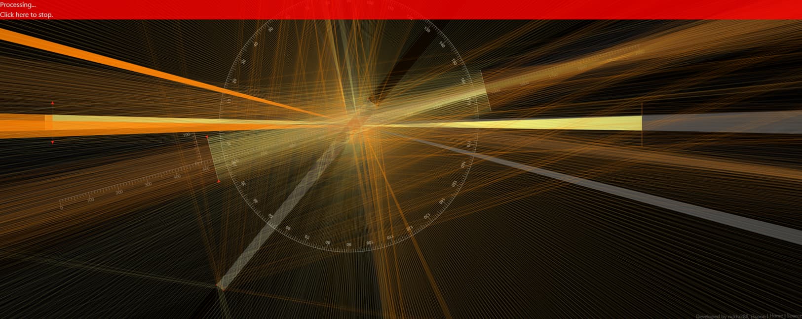
Higher ray density view:
Extended Ray view:
Here you can see the output from the cavity in the top-right corner. Further proof the cavity is working.
In process of adding more percentiles to the relative intensity spectrums. The red is the percentiles in relation to the pump, and blue is in relation to the emission. The emission percentiles can be used to find median tuning ranges for each of the samples depending on the pump wavelength.
Update: Completed analysing the spectrums now. The main post has been updated with concise info on each sample.
I will update the main post periodically to summarise the project stages. So I now have a better idea of what sample should be pumped with what wavelength, and what sort of output I can expect out of them. Still in theory, proof is in the experimentation. Optical layout is essentially finalised. Only thing I may add is a birefringent filter/tuner, as like any dye laser, these are tuneable. I will look for an appropriate one and add it to the optical setup. If these samples lase, we could end up with reliable output across a wide part of the visible spectrum that we most desire. Also in CW a hopefully higher than DPSS power output too.
I am now starting 3D modelling stage. This will end up being fully custom built. I own a 3D printer at home, and I have access to 3D printers, a C02 laser cutter and a CNC router (if I can return it to working condition) at work. Every mount will have to be designed by myself. I have examples of others work. But mix and matching mounts won’t work so well.
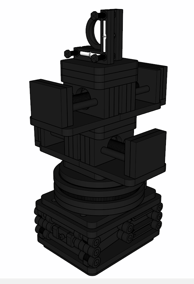
My plan is to make this cavity able to account for manufacturing errors by having full XYZ control on the mirrors as well as tilt/rotation. So essentially built in 5 axis control for every optic. So there will be a lot of mount stacking. Best avenue will be in this order.
Z lift platform, X linear translation stage, Y linear translation stage, rotation stage and kinematic mirror mount
Custom Optic Stages/Mounts:
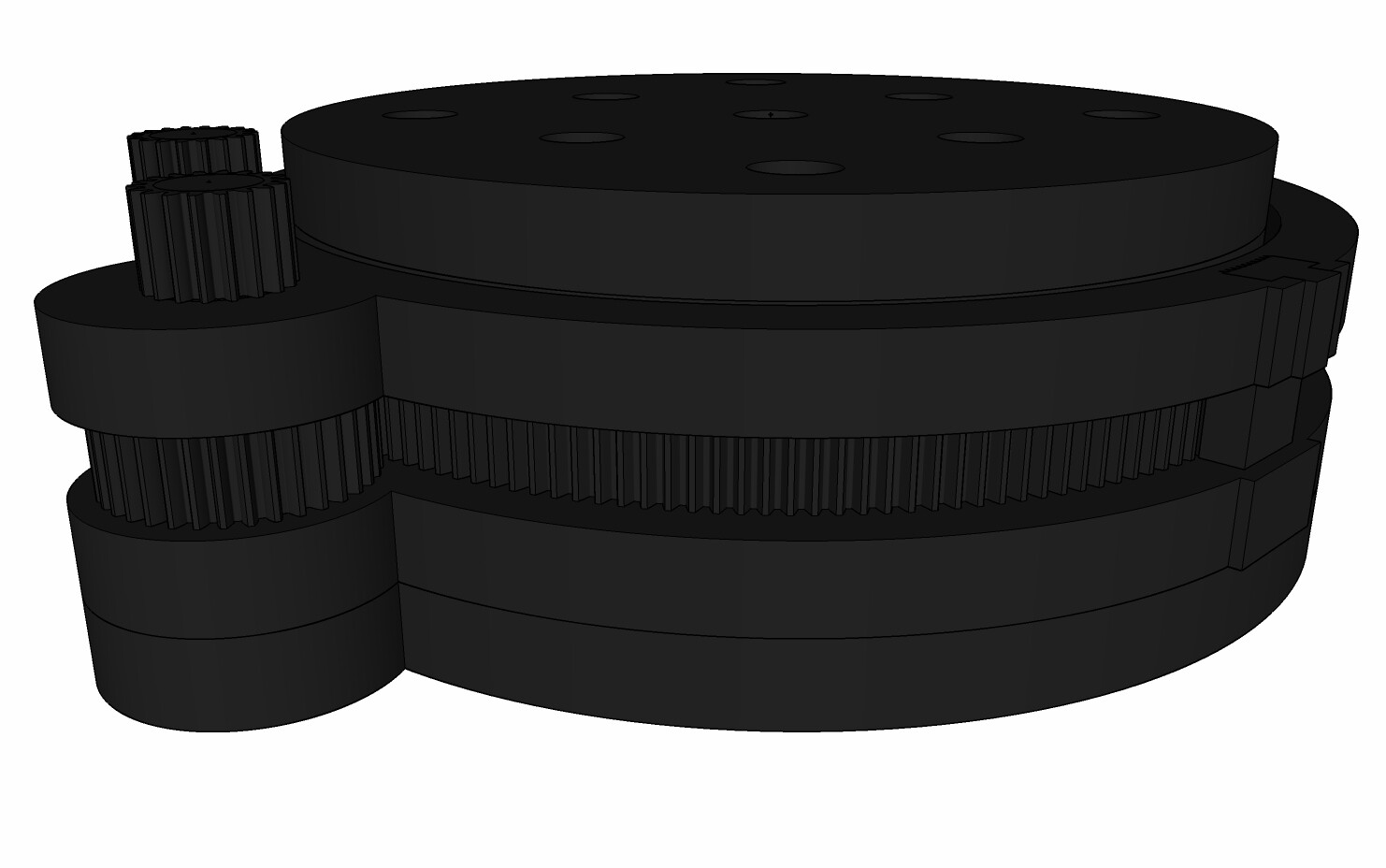
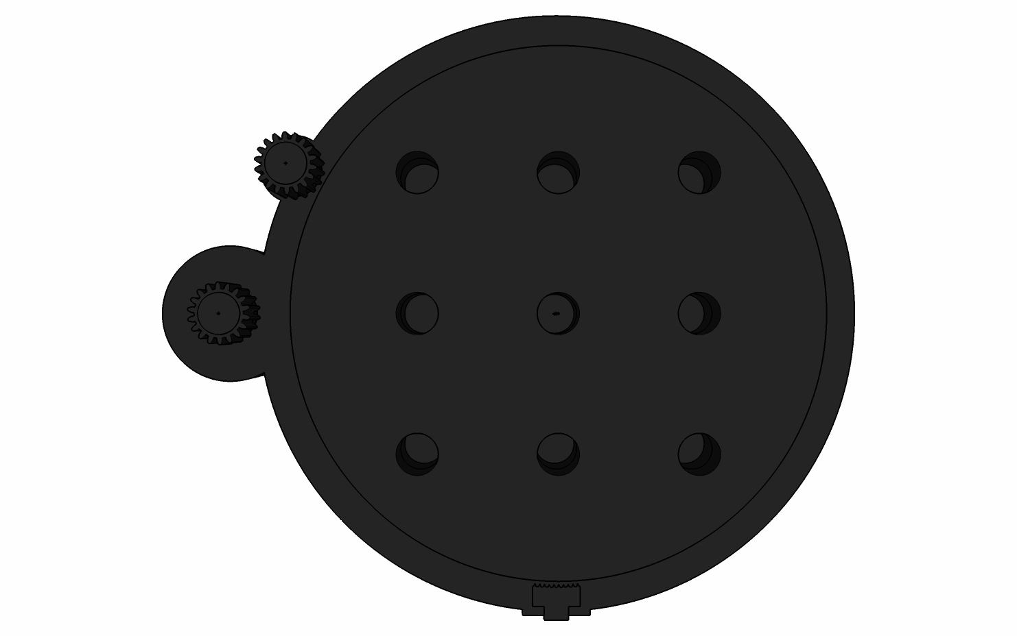
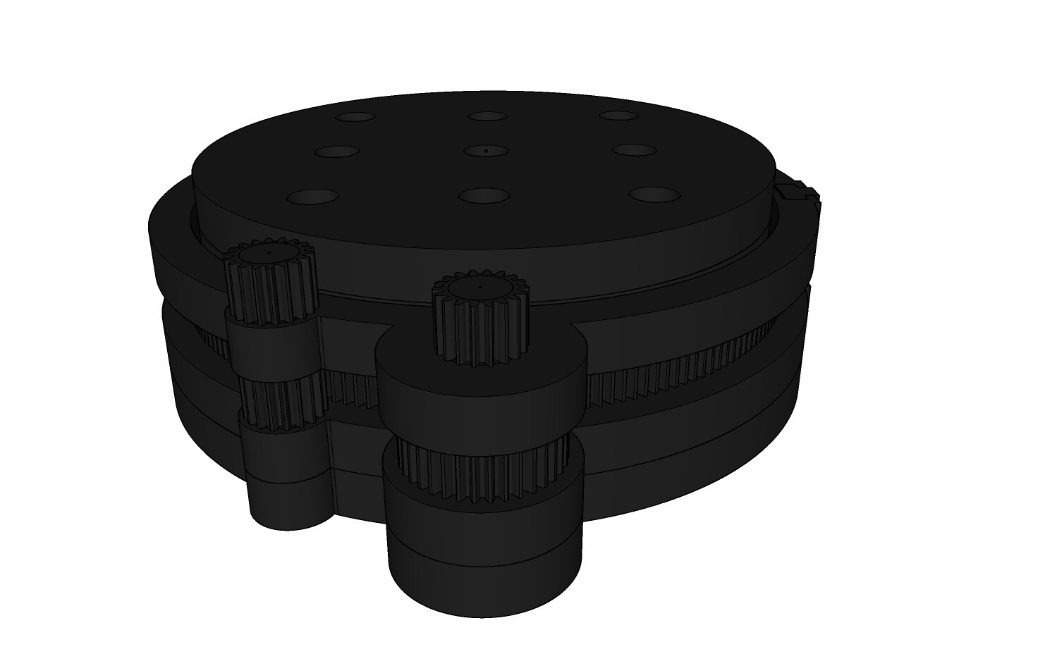
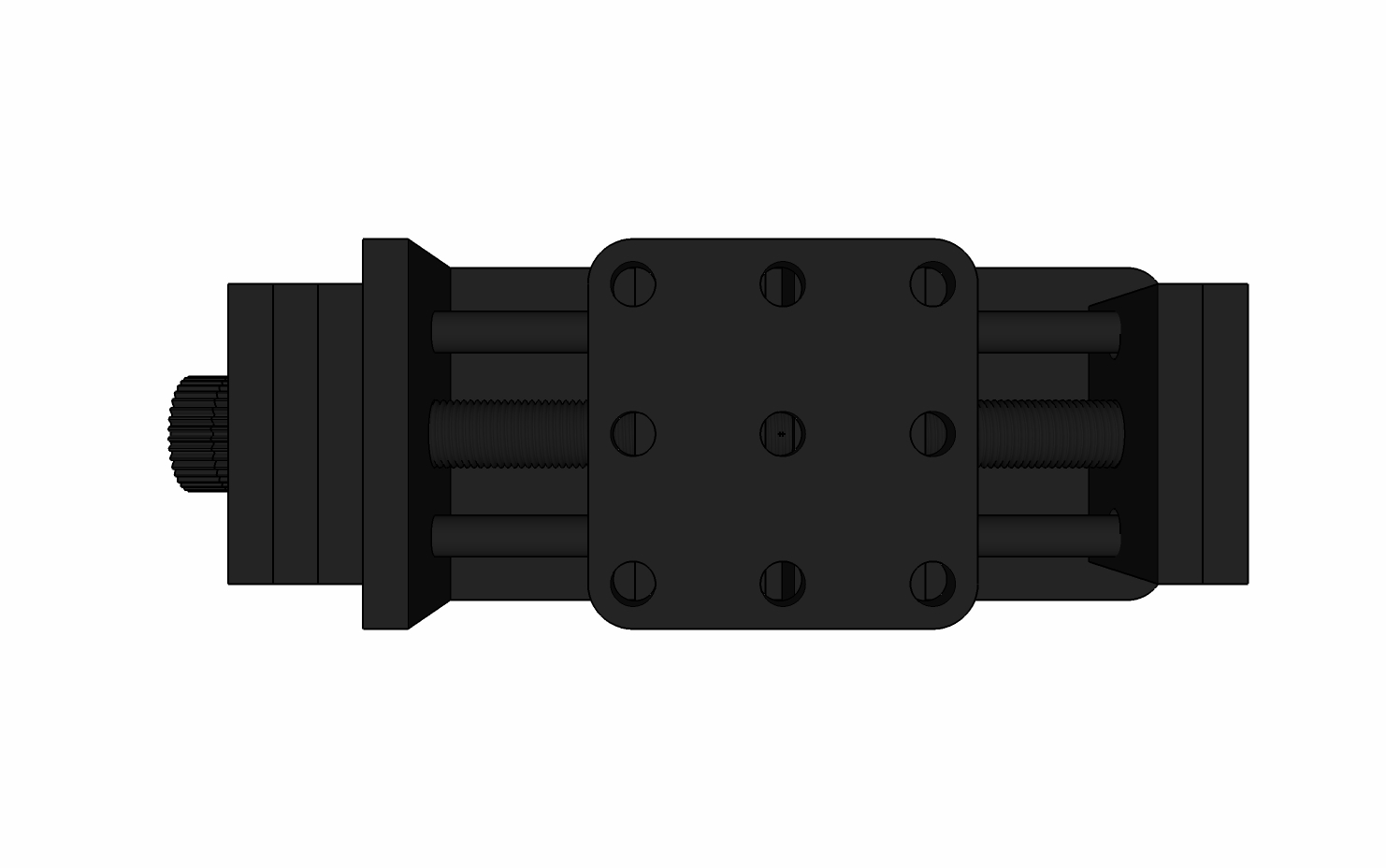
Rotation Stage:
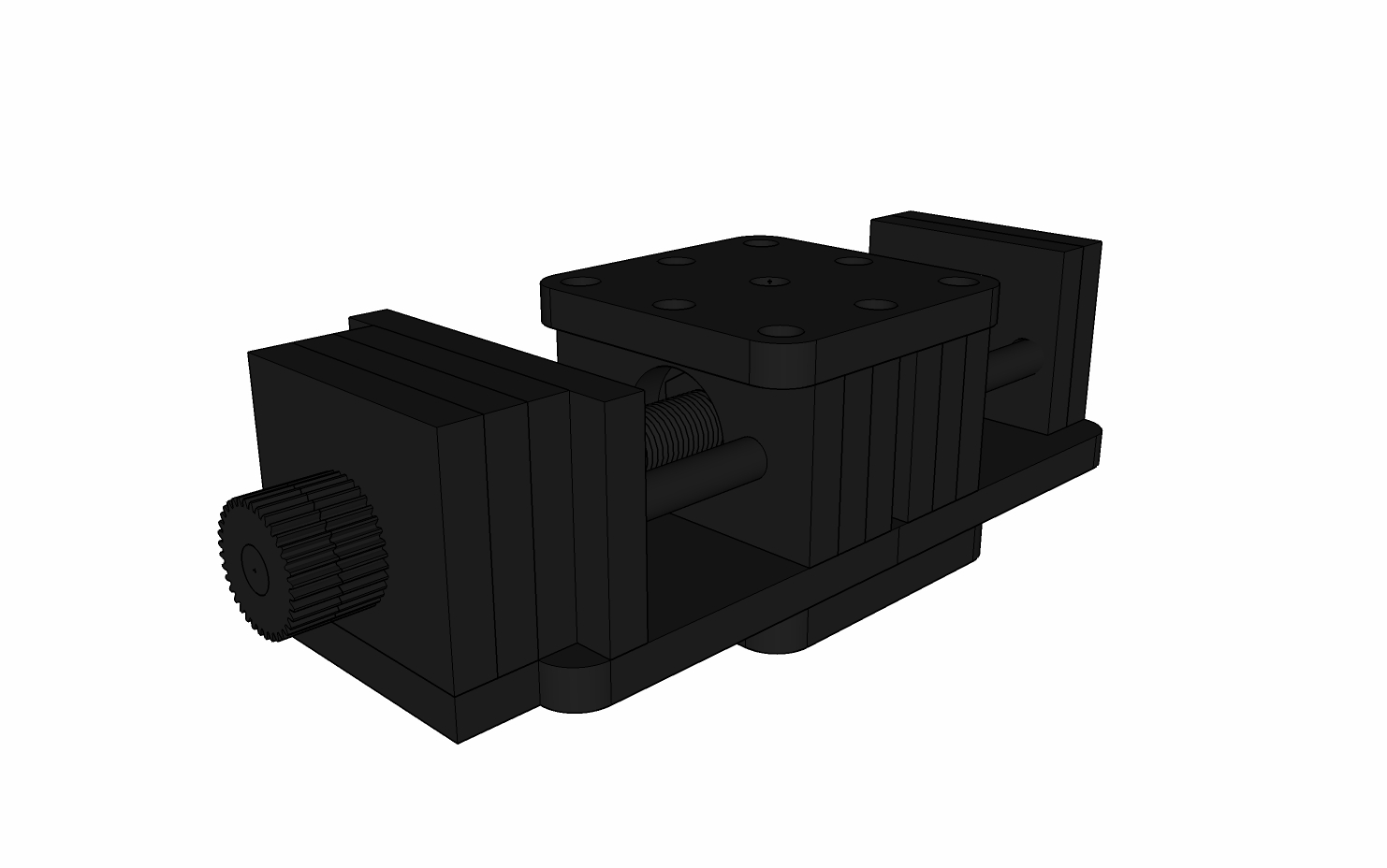
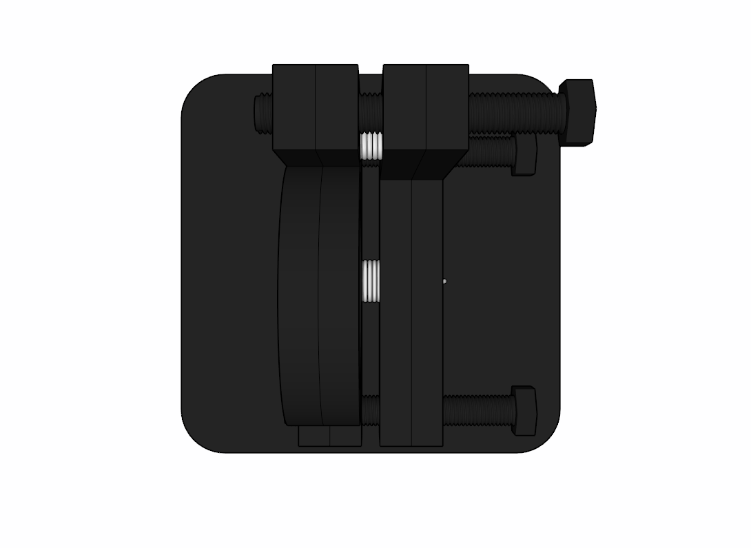
Translation Stage:
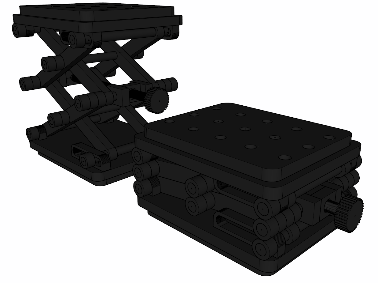
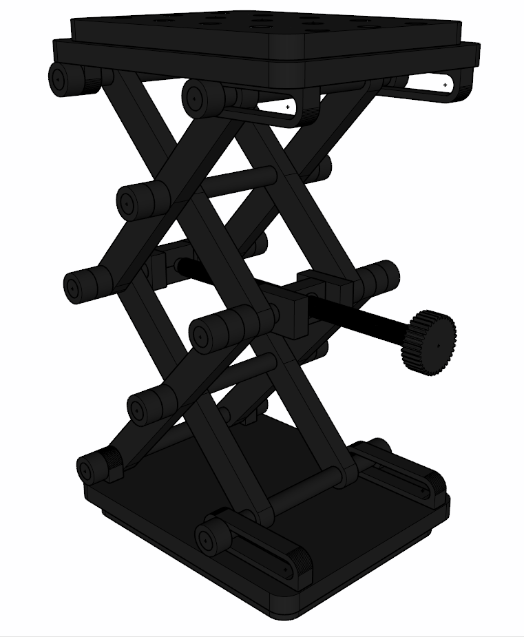
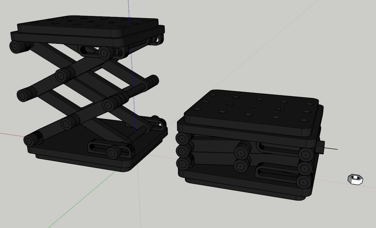
Z Lift Stage:
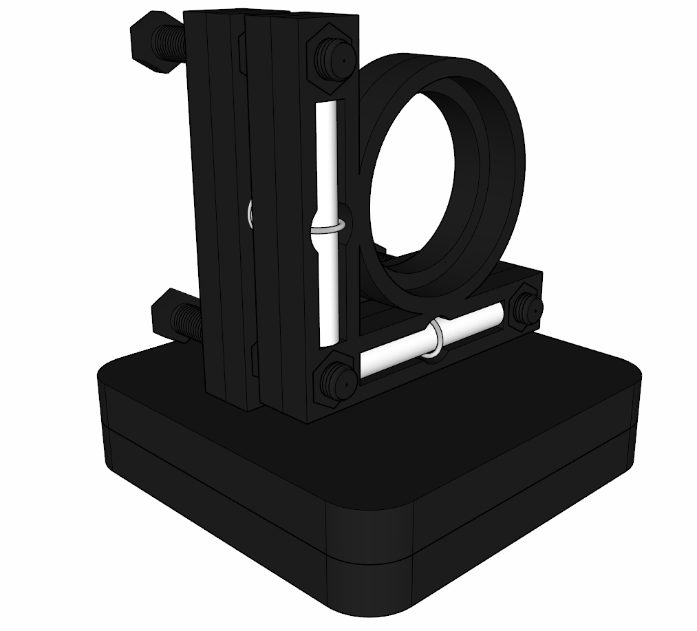
Kinematic Mount:
Combined:
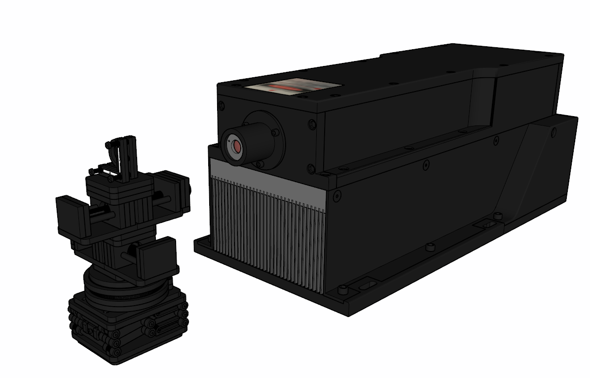
Combined (With Laser Source):
1 Like
Curtis, your best judgement is what I am happy to go with sir.
I am on vacation in Odessa, Ukriane for about two weeks. How to send needed funds? Paypal?
Chris
The output coupler is hard to purchase for me in the UK. I would need you in Ukraine to get it delivered to you first, and then shipped to me. I need to have a UK VAT number in order to purchase it myself. I feel a tad uncomfortable with having another spend out on the components if this doesn’t work out. So I will likely look at investing in the other mirrors and only have you help on the output coupler due to logistics. We’ll discuss funding in the new year. Let’s get Christmas out of the way. It will give me time to plan this project out 100% before committing too.
I’ll be continuing to work of the CAD design of the laser system, and we’ll go from there. I’ll keep updating this thread both as a log of research/work and so you know what is going on. I’m working on designing a Z/Lift Stage atm.
All of these stage components would cost an absolute fortune if purchased so designing and making my own will help the project along nicely.
Have a great holiday! Also have a great Christmas.
1 Like
OK, might be better to send to Qatar after return on Jan 7th?
1 Like
Let me check. Qatar would work, you would have to select ‘Other country’. However shipping is more. $45.20 for Ukraine, $79.11 for Qatar. Total cost of OC would be $299.48 for 1. $519.85 for 2 if you bought yourself one at the same time.
OK, as long as before I leave Ukraine on Jan 7th. I won’t want one for myself until after proven.
Understandable. They are not in stock so would be unlikely to arrive in time for Jan 7th even if bought now. So it will have to be when you are in Qatar.
I’m more interested in supporting you on this project than building one myself, truth be known, but I might want to do so too.