I am not sure if someone is even reading this. But at this point i am committed and will post everything to have at least some reference documentation for me.
Whats next?
We are still missing the SOC and its connections to all the components.
Programming is also not possible right now. So i will do that first to have the USB part done!
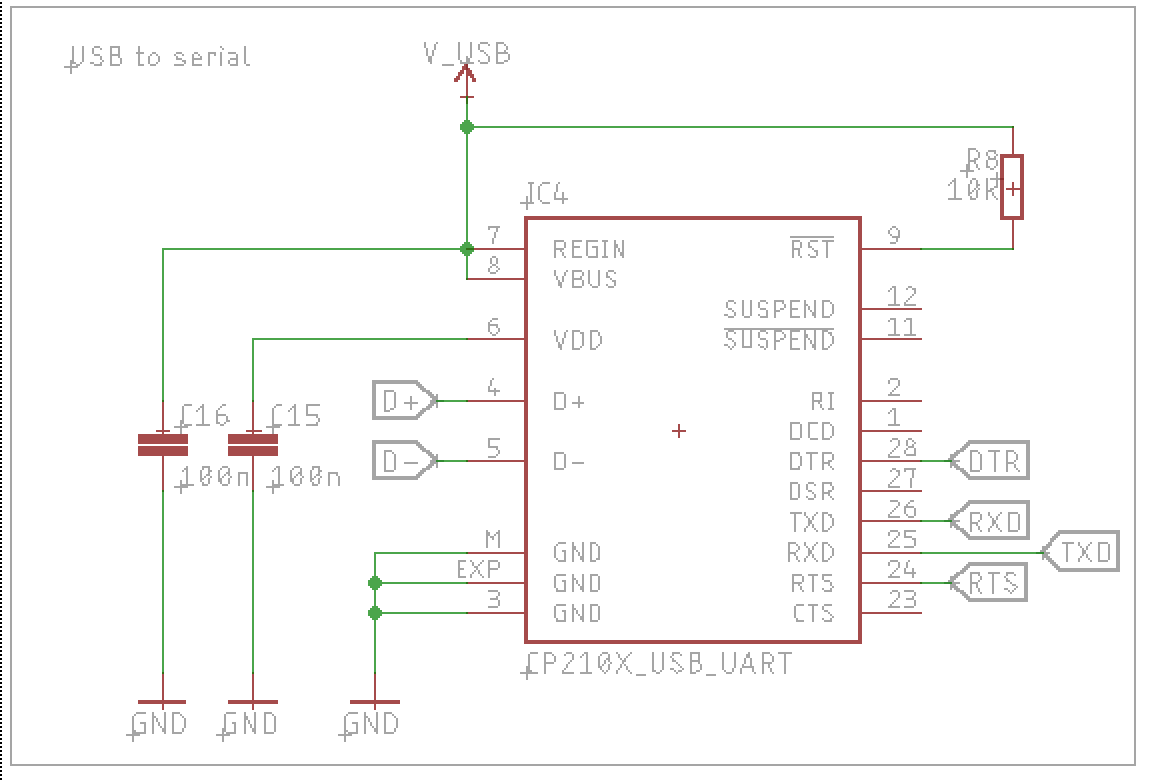
I will need to convert the USB signal to serial. The ESP32 uses serial to upload programs to it and to talk to a host.
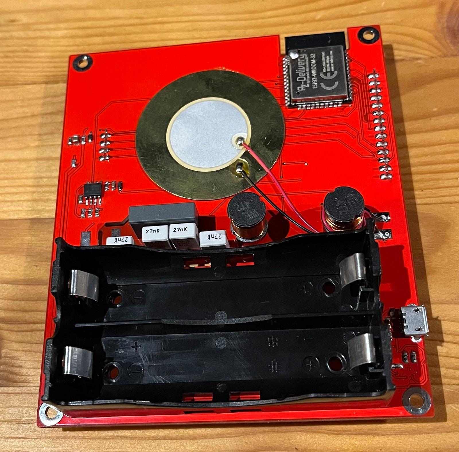
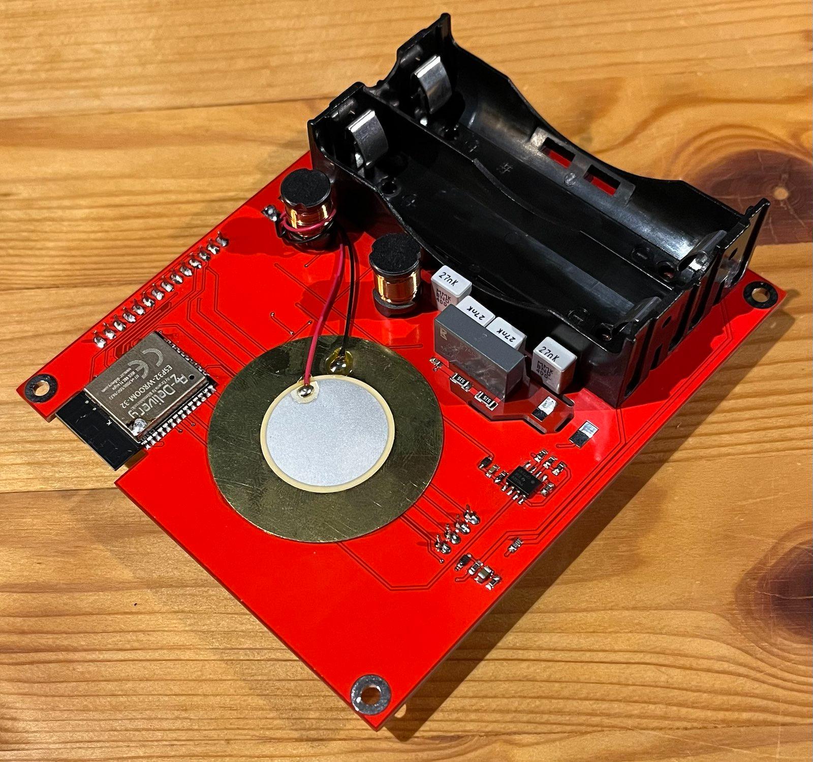
I will use a CP2102 as a USB/serial converter. Its found on most ESP32 breakout boards so i can just buy a NodeMCU and harvest the ESP32 and the CP2102 from it.
Its easy to use. Just connect some decoupling caps and pull reset high to make the chip provide a serial connection.
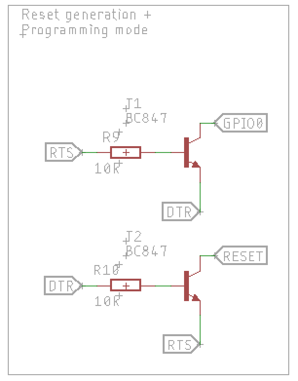
A little something is still needed: to program the ESP32 it needs to be reset while a special pin (GPIO0) is held low to signal the SOC that it should not run its saved program but rather receive serial instructions / a new program.
The DTR and RTS signals are used to set the ESP into programming mode. Two transistors are needed as gates to archive the right logic:
Only if DTR is high and RTS is low, reset is pulled low.
While RTS needs to be high with DTR low to pull GPIO0 low.
Programming is now possible with Arduino or ESPtool just by connecting to the USB Port.
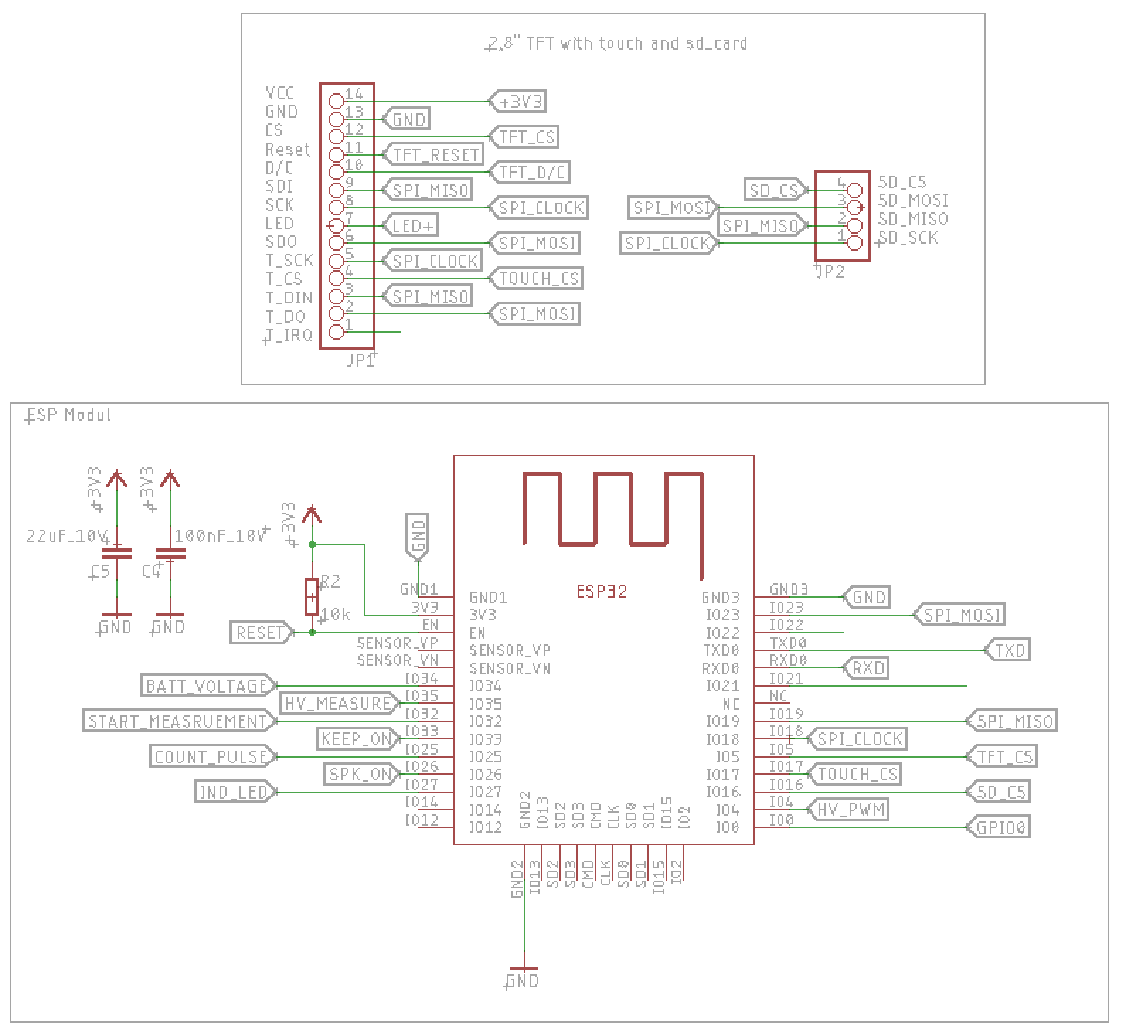
Next up is the ESP module and display.
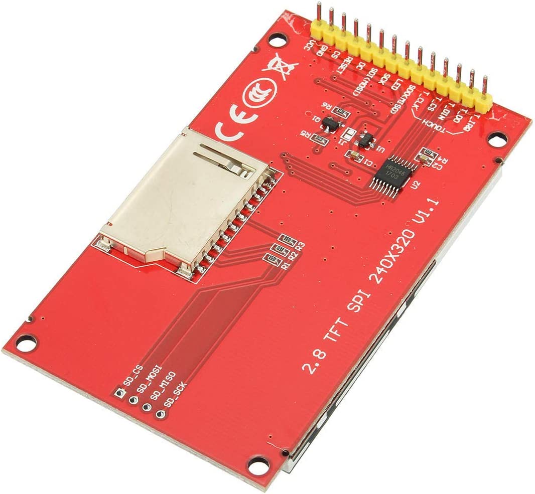
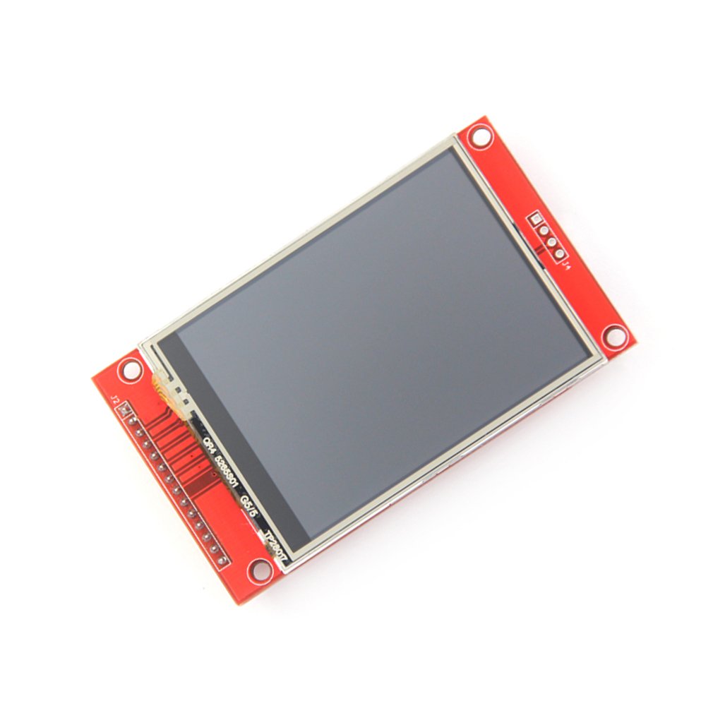
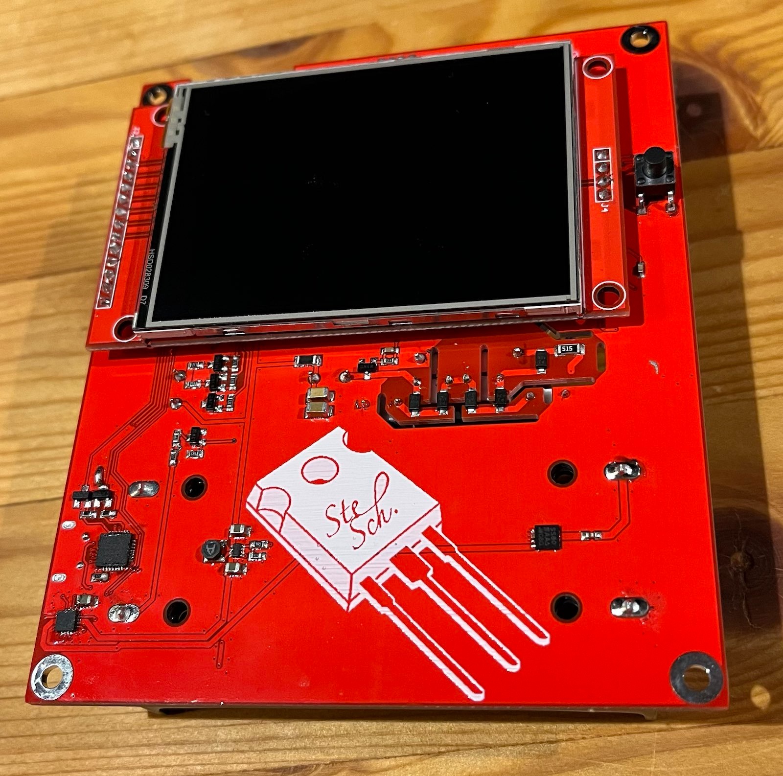
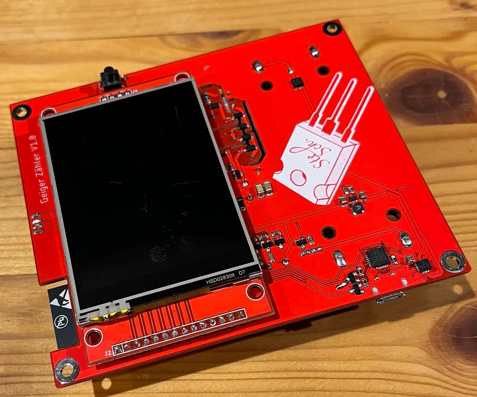
I will use a 2,8" TFT touch display on a breakout board. I cant be found by searching “2.8 Zoll TFT Touch LCD Display ILI9341 240x320” on aliexpress.
It features a SPI bus for the TFT, Touchscreen and SD card.
The SPI bus is shared between all of the endpoints and just uses a single chip select pin to ensure the SOC is talking to the right endpoint.
I am not sure if i will ever use the SD card but connecting it does not hurt.
Might be that i need some other pins to control some functions. I will add them later.
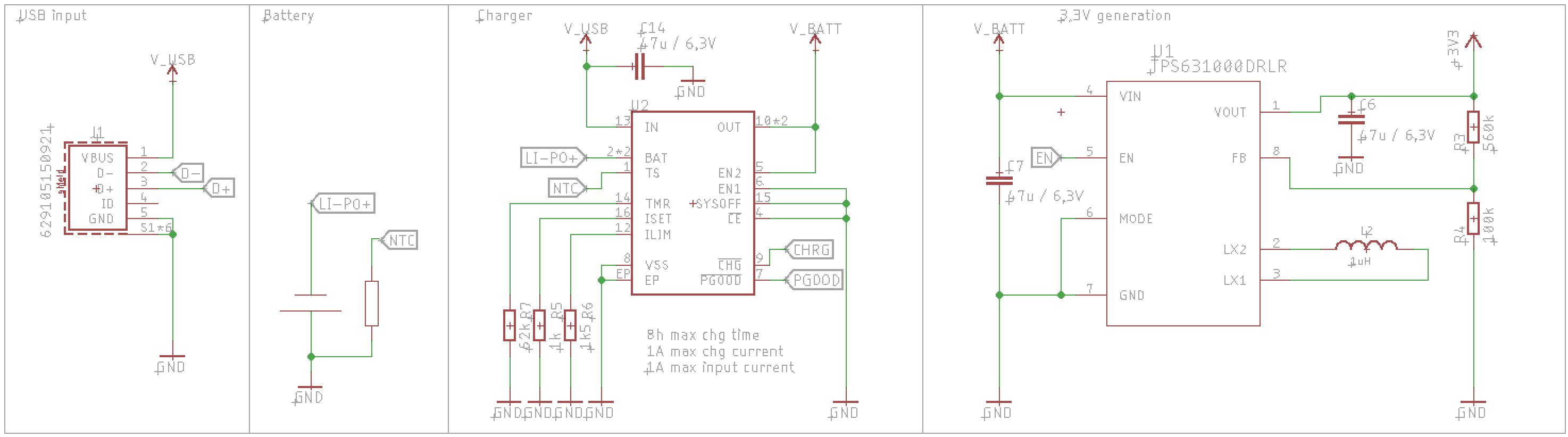
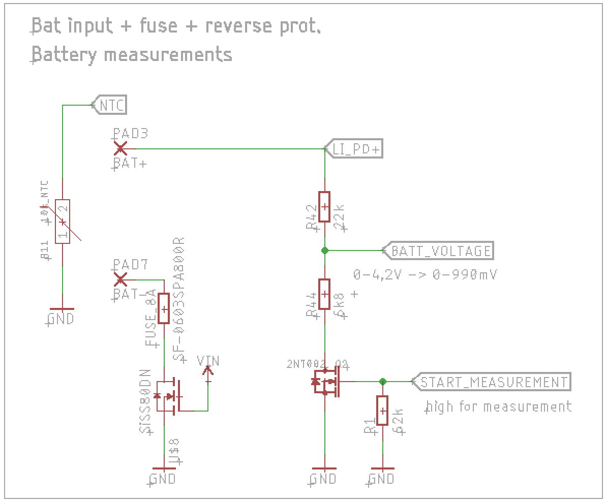
While i did the charger for the 18650 cell, i did not yet implement reverse polarity protection, fusing and voltage measurement.
Measurement is done by a simple voltage divider. To not waste power, a N-Ch fet is used to switch it off while the unit is off / no measurements are done.
Fusing is also easy: just a simple 0603 SMD fuse. If it blows, something is horrible wrong as the charger IC features short circuit detection, so soldering is necessary, no need for a easy replaceable fuse.
For reverse polarity protection, i use a N-Ch Fet.
The NTC is connected to the charger IC that suspends charging at too high and too low temperature.
Thats it for the battery and uC.
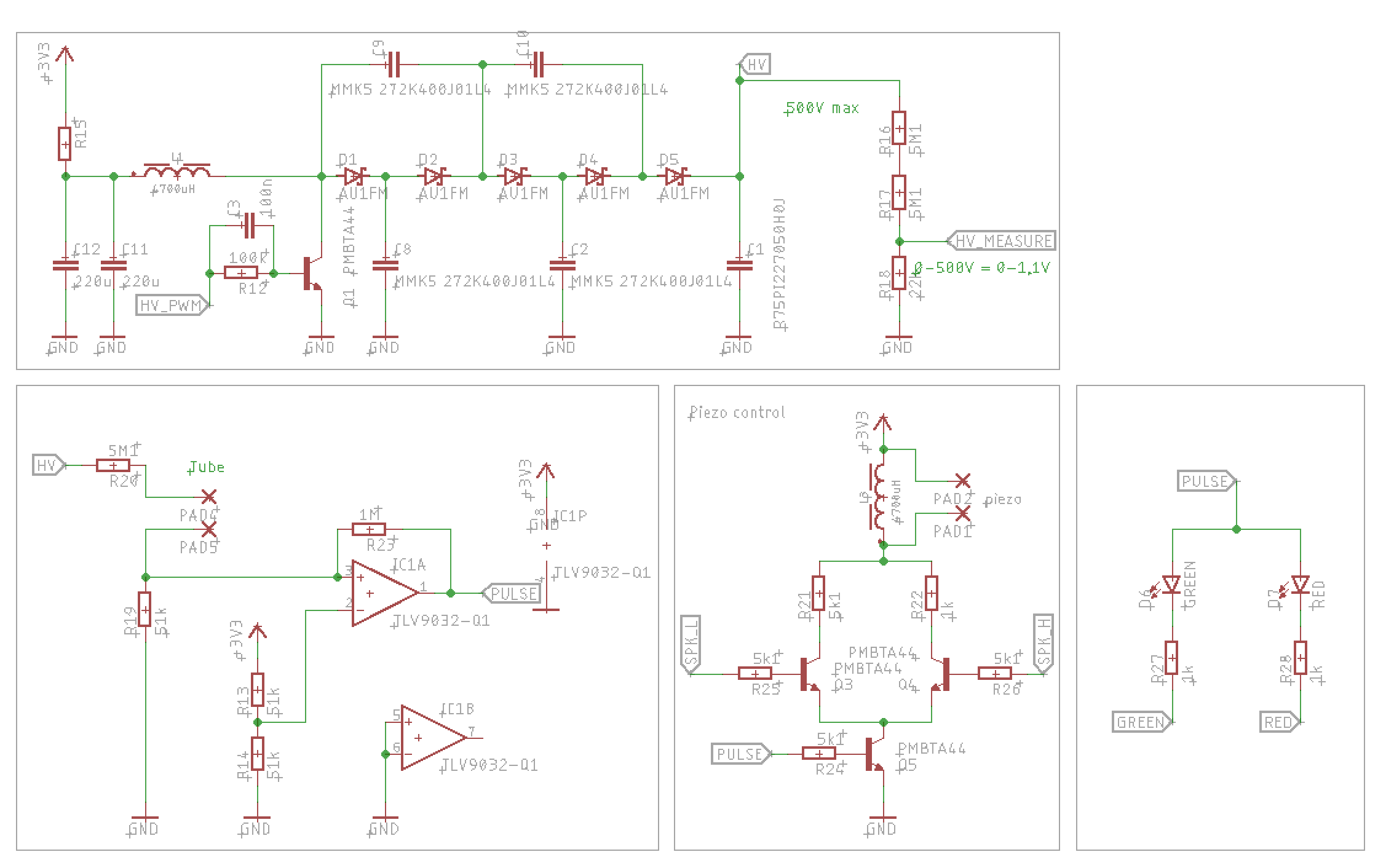
Just the tube count interface, the speaker, indicator interface and HV generator is left to do.