Hey guys,
I have now fiddled with the resonator(s) for probably about 20hrs, no luck yet. I have two main problems that I didn’t really anticipate, although I definitely could have.
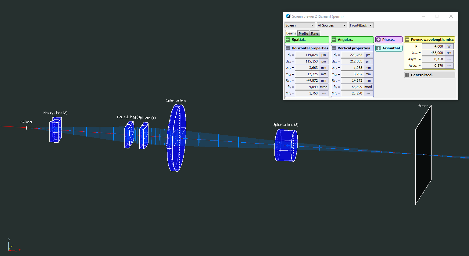
1. Energy density in the crystal. One issue is the focussing inside the crystal, which of course is directly connected to the pump module. Either the glue drifted a bit or builder was right and my alignment was not as good as I thought. Either way, two spots (1 green and 1 blue) overlap very well in the crystal, but the third one is way off and totally blurry, so the PBS and collimation train of the 2nd blue diode are off. Is there any way to soften/remove cured UV glue? But just the overlapping spot has 4W blue + 1W green which should definitely work. The other issue related to this is defocussing by the pump mirror. Remember that the beam is focussed through a plano-concave mirror, which increases the spot size a lot.
It about doubles the diameter in both dimensions (so only 25% power density)… No paper ever mentioned this though they must all have gone through this issue! Makes me wonder if much below ~50x50um spot size is even possible in these circumstances.
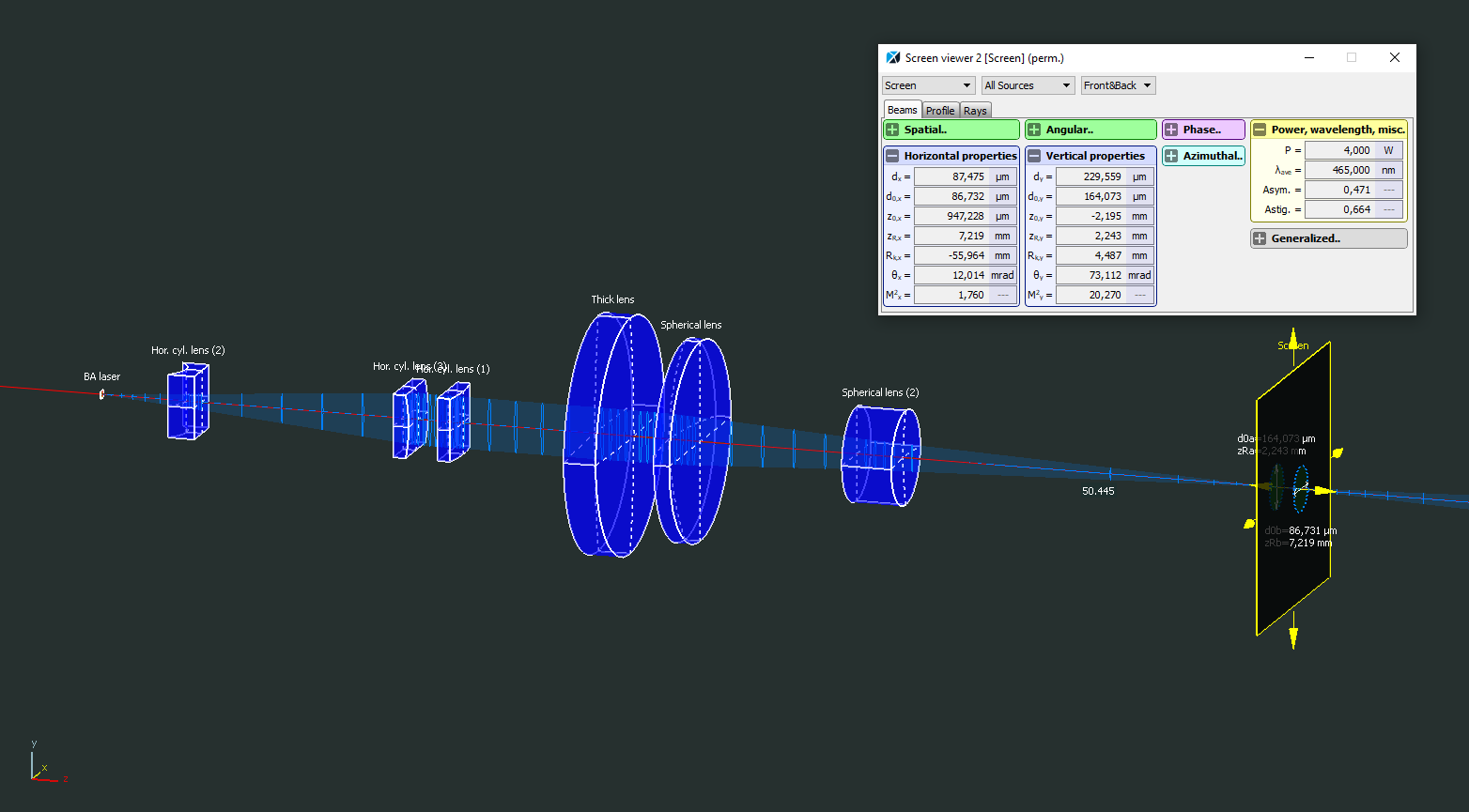
I do happen to have a f 250mm achromatic lens that corrects this a bit, but still, its about 57% of the originally planned power density.
This setup did not work either.
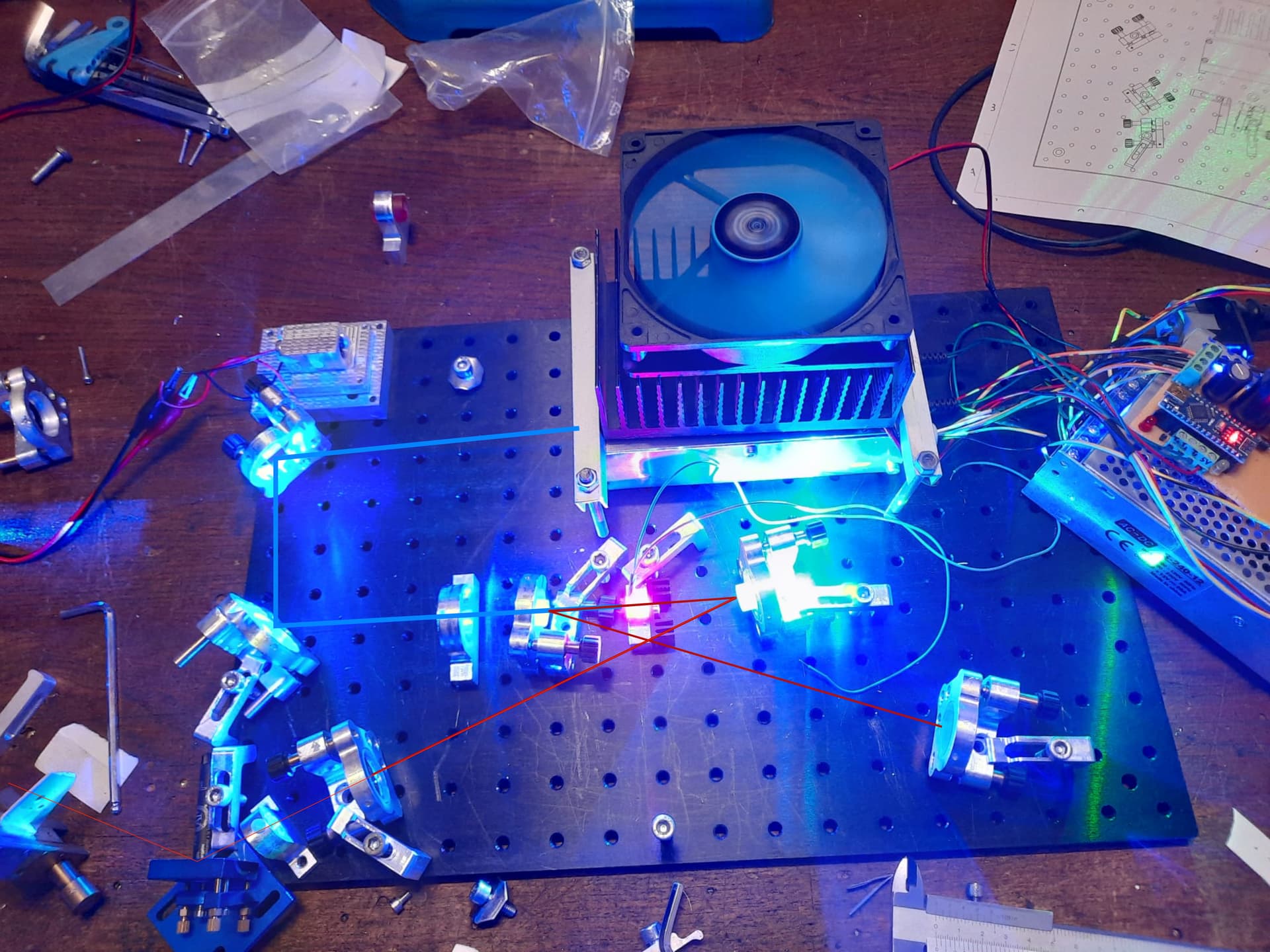
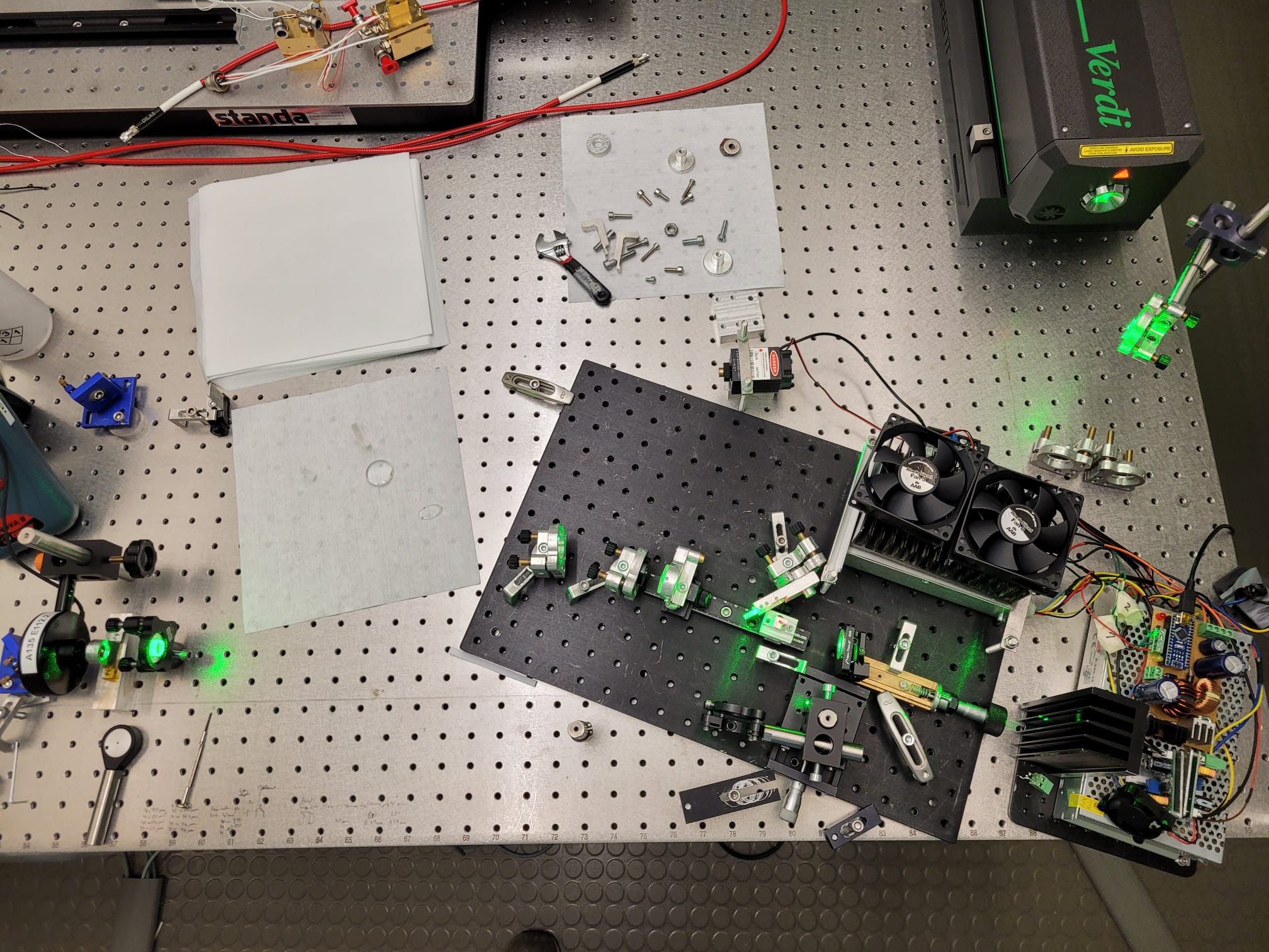
2. Resonator alignment. The original plan was to use a x-Fold four mirror cavity, which is reported all over the literature. Aligning this resonator has not worked out for me yet since my alignment laser (1mW HeNe) fades out quickly after so many bounces. The Pr:YLF laser at 640nm (and tens of mW at the lowest pump power) works way better, but still, no luck. I suppose the difference in index of refraction between 640nm and ~800nm leads to problems since the crystal is brewster cut. Here’s a pic of the resonator by the way:
One issue is not only making sure that the resonator is aligned but that the pumped volume also overlaps with the mode volume. I can definitely do this in principal using the 2 pump fold mirrors. I align the resonator by coupling the Pr:YLF into the outcoupler (bottom left) and overlap the spots (simplified…). One could think that I should just get the pump beam to retrace the alignment beam back to the pinhole on the bottom left, but again, the index of refraction is a problem.
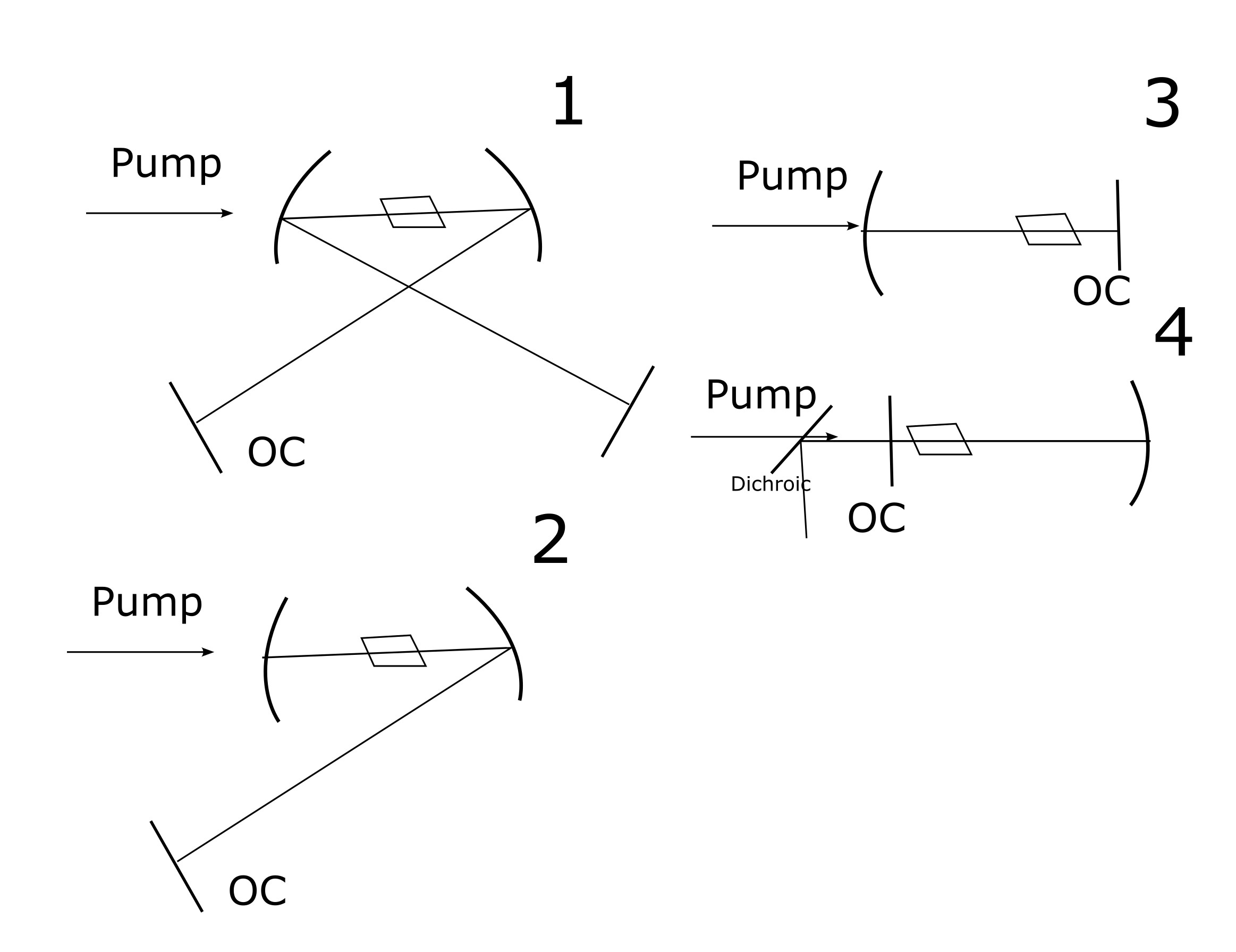
So, I thought about it and sought to simplify the resonator. Although I must say that I have never seen a different TiSa Resonator other that x-Fold or more complicated. Generally its for astimatism compensation of the brewster cut crystal I think, but is that even important for cw-lasing? I don’t know.
So I started by eliminating one plane HR mirror by folding one concave mirror directly back into the crystal, essentially creating a V-fold (see 2). Didn’t work. Then I used the simplest resonator I can do with my mirrors: a hemispheric one. This one was risky since the plane outcoupler reflects some pumplight back into the diodes but luckily I didn’t destroy anything. Alignment should be no problem essentially since I’ve done that tens of times with other lasers, but still, no luck. I tried resonator 3 at first, but then thought I could drastically reduce the spot size by using shorter focal lengths for the pump lens. With 4 this is possible (remember, the resonator length for 3 and 4 is 100mm). A dichroic should then separate the pump and IR. Neither setup worked, so maybe the pump is insuffient / OC has too much outcoupling. Although in the literature, this combination has worked fine! So I am torn whether just bad alignment, bad pump quality/power density or too much outcoupling is the bottleneck here. By the way all resonators are stable at least in theory (checked with ReZonator 2.0).
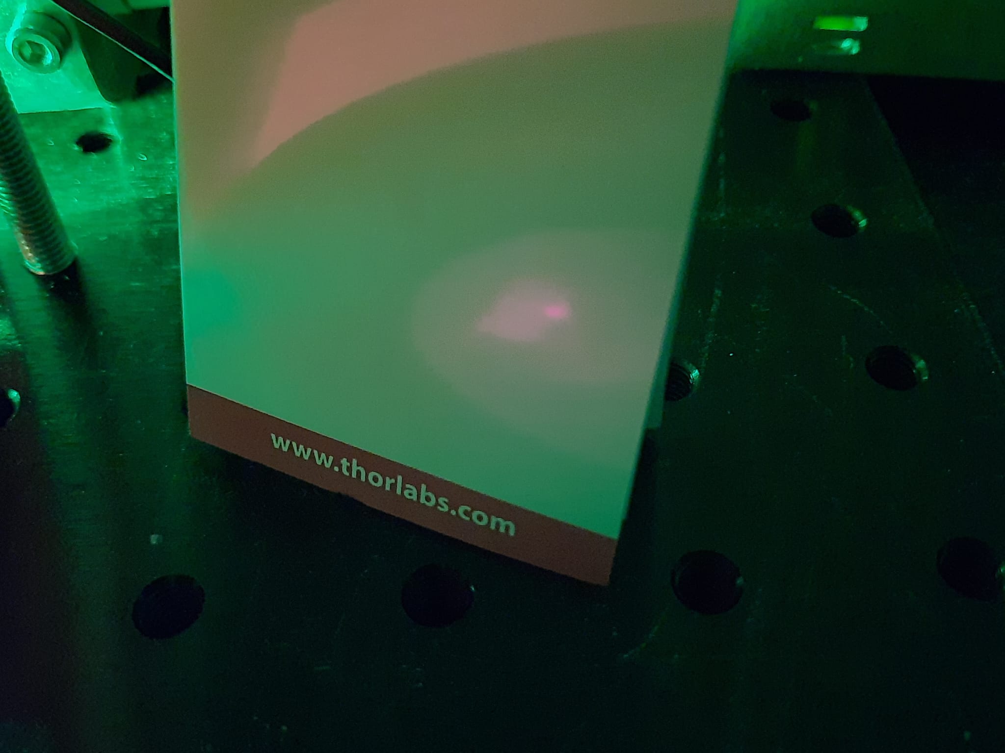
Although I can report that I have seen some IR fluorescence from the crystal, though very dim:
This is on resonator 3, but also worked with 4.
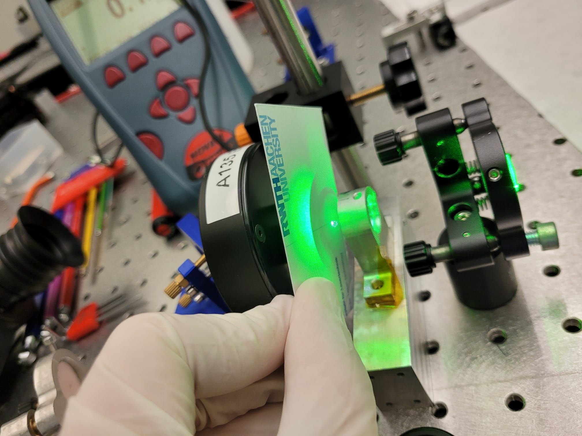
Here’s also a video . I recognize this spot behaviour from my other hemispheric resonators, but overlapping the spots produced no lasing. Especially the tighter spot has high divergence and fades quickly so this is no laser action. Maybe 1 and 2 produce this as well but since the distance from crystal to OC is so much larger, it may not be detectable by my camera anymore.
So here I am, wondering if laser action is shortly around the corner (just one more hour of alignment!) or if my setup can work at all.
I have also ordered a 808nm laser module for alignment, this should have no issues regarding different index of refraction and shouldn’t fade from the reflections due the mirrors being HR for that wavelength. Have to use my camera for alignment is really annoying though. But if it works, why not.
I might also make a post on photonlexicon for that issue since I’ve read some posts where peoply claim that they have experience with TiSa, which is really rare… I only have till January to get this thing aligned (semester abroad begins at 12.01.) so I am a bit stressed out
Anyways, as always, I’m always happy about comments!
Nik