Diode pumped Ti:Sa Laser

Hello people,

warning: long text :slight_smile:

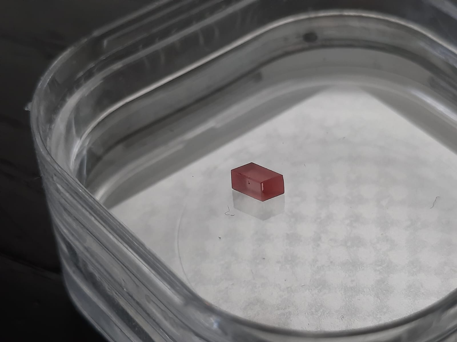
whilst I am working on the DPSS Nd:YAG Laser, I am planning a DPSS Titanium Sapphire Laser, cw at first, possibly modelocked later. I have actually already made a few crude experiments which did not succeed. I do have a 19mm long Ti:Sa crystal (chipped at one edge, only 4x4mm usable aperture, which is a bit scratched up) and the mirrors for a x-fold resonator (2x concave R=100, AR VIS, HR NIR; 1 HR NIR plano; 1x OC 95%R NIR plano). Also, I’ve got a NDG7475 1W 520nm diode. With those elements I have tried the x fold (really difficult to align) and an experimental hemispheric resonator. Neither have succeeded. I suspect that the available pump powers and the high OC transmission play a role. The crystal may be very long, but it is doped in such a way, that is aborbs ~70% green (54% blue), just like shorter crystals. So the only problem is getting the rayleigh length of the pump long enough to sufficiently pump the whole crystal.

After identifying those problems, I think that cranking the pump powers way up may be the solution. I’d like an OC with lower %T and a shorter crystal, but those are what I have atm.
In the following, I’d like to show the thinking and designing process behind the new pump module and would be extremely happy about feedback, especially criticism!
Now, I am going to use 2x 5W 450nm diodes and 1x 1W 520nm diode for pumping. According to this source, wavelength multiplexing increases efficiency since 450nm pumping induces a pump induced loss which 520nm pumping rectifies. So I can have high pump powers with low pump induced loss. Also, this paper shows that my pump powers should be able to threshold a TiSa crystal even at >5%T. However, they used crystals of only a few mm length, which I dont have. Anyways, I will use a polarizing beam splitter for combing the 2 450nm diodes and a dichroic for adding the green diode.
Beam quality is a big issue for diodes like this so it is imperative to correct the beams. I plan to use cylindrical lenses for that and after talking to Phillip at Live Lasersystems I’ll definitely use FAC diodes since I dont need an aspheric collimator. A FAC diode costs ~90€, a non FAC + aspheric lens ~80€ so its a no-brainer imo since the FAC approach gives much better beam quality. For the green diode, I’ll probably use my M9x0.5 collimator + anamorphic prism pair since this is what I’ve already got but I’m not sure right now. Since the beam profile of the collimated 450nm diode will still be a bit elliptical and I would have to have the two beams at 90° rotation to each other to combine them in the PBS, I’ll also use a waveplate on one diode to rotate the polarization without having to rotate the diodes.
Another point is getting the diodes collimated in such a way that the rayleigh length for the pump beam after focussing with my F80 lens is correct for the crystal. But what is “correct”?
The following calculations are purely my thoughts so they may be flawed. If so, please tell me :wink:
Please have a look at this screenshot:


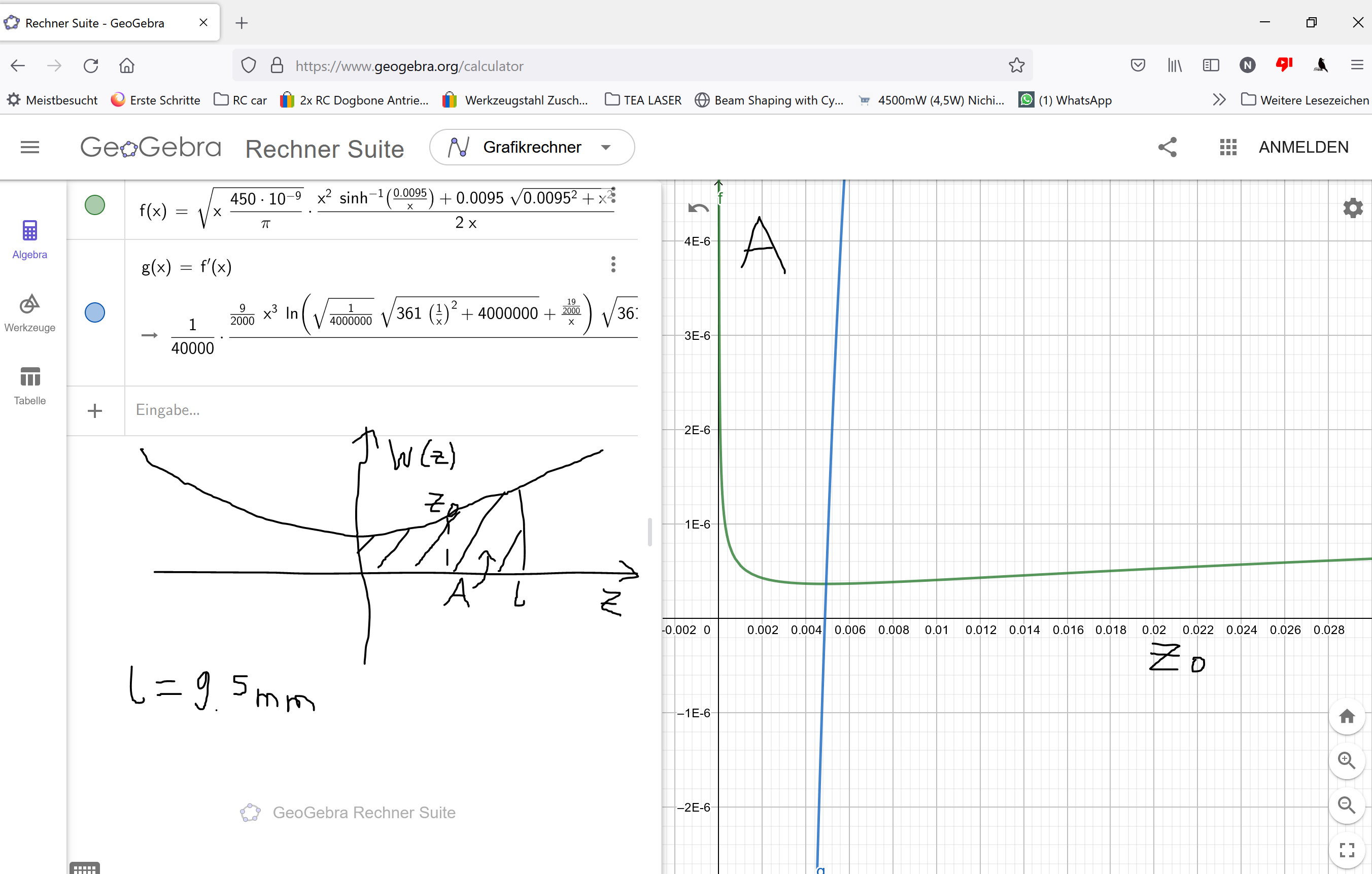
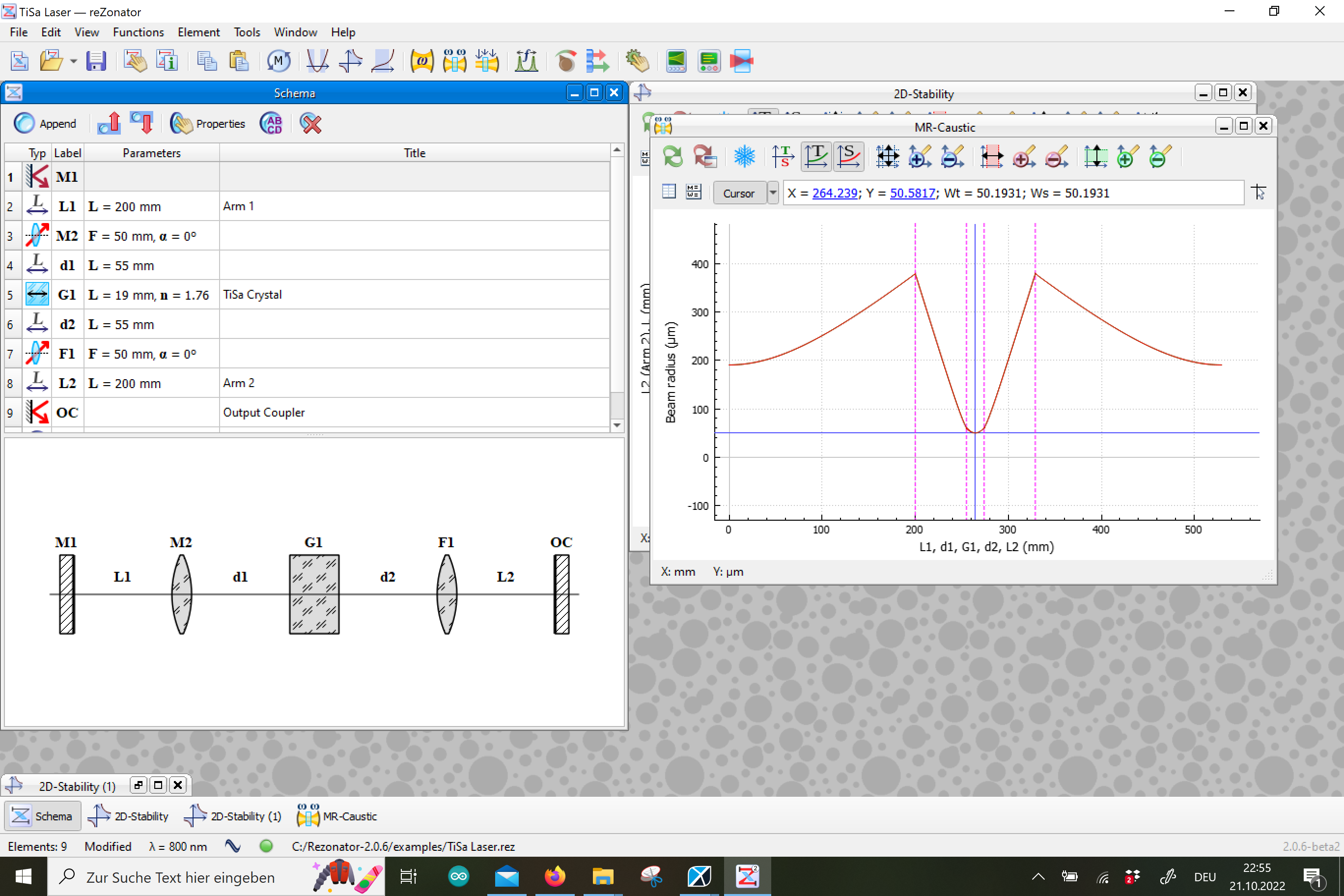
The scribbled graph is the beam waist w(z) on the y axis and the progagation length z on x. The area A is the pumped region (2D-simplication) within the crystal, at z=0 lies the focal point and at z0 lies the rayleigh length… Actually, the absorbed pump beam would be from z=-l to z=l and from w(z) to -w(z) but because of symmetry this simplication works for the following thoughts. Now what I want, is to minimize A to get maximum average power density in the pump beam. I can’t just make the focal spot really small since the rayleigh length would decrease and the edges of the crystal would not be pumped well (and vice versa). So there must be an optimal rayleigh length z0 for a given l. So I integrated w(z) (for gaussian beams, not true here, but an approximation) from 0 to l to get A. A then is an expression dependent on wavelength (given: 450nm), l (given: 19mm/2=9.5mm) and the rayleigh length z0. Thus, the only variable is z0 and I can plot this in 2D. Remember, I want to minimize A so I find the lowest point of the curve A(z0). I can already see this point at z0=5mm, but let’s have fun and derive A(z0). A(z0) is minimum (or max), when A’(z0)=0. This is, again, at z0=5mm.
So, we get that the optimal rayleigh length for the crystal of 19mm should be 5mm, presenting a good trade-off between pump density and longitudinal pump uniformity.

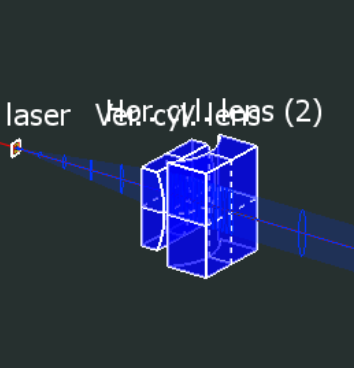
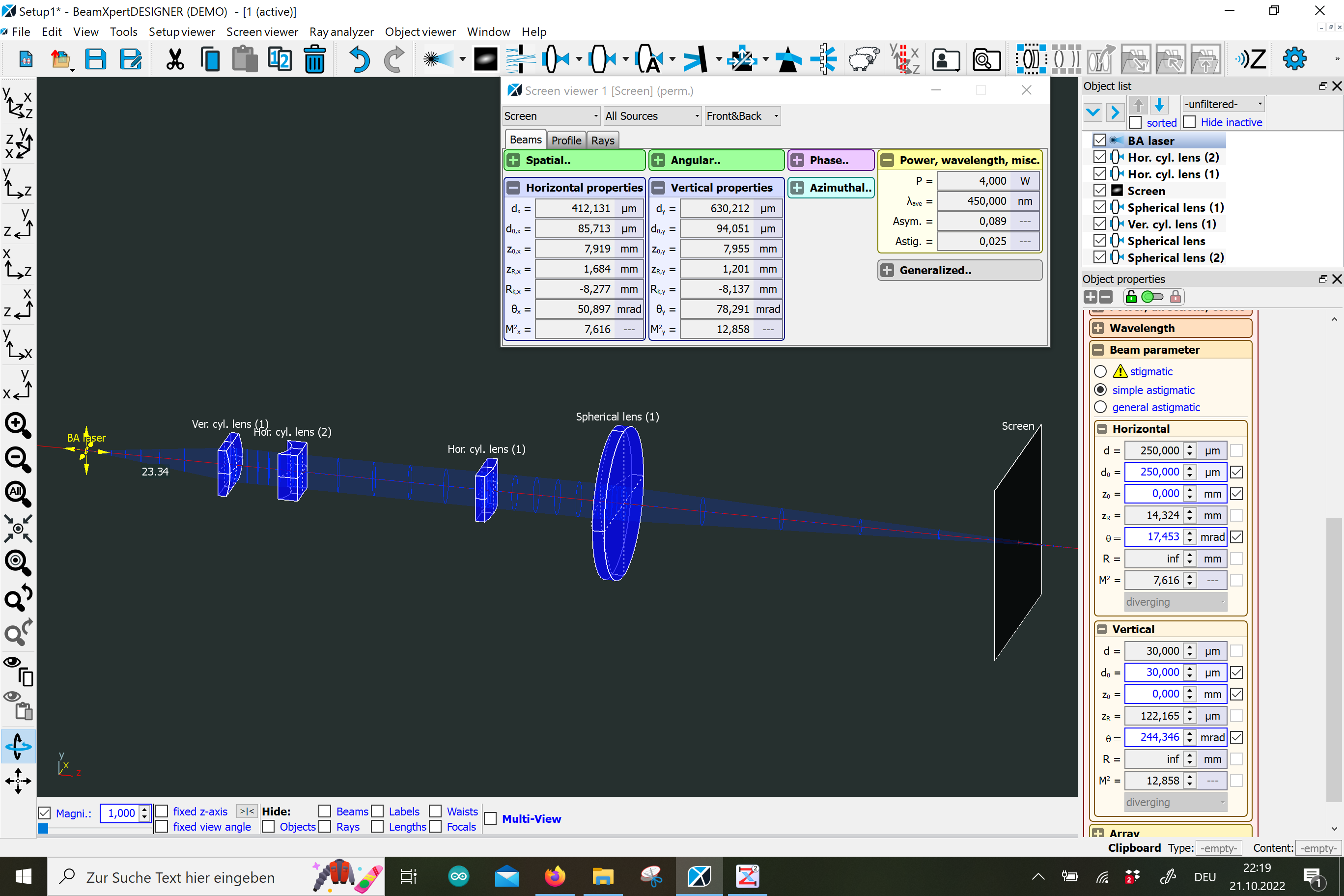
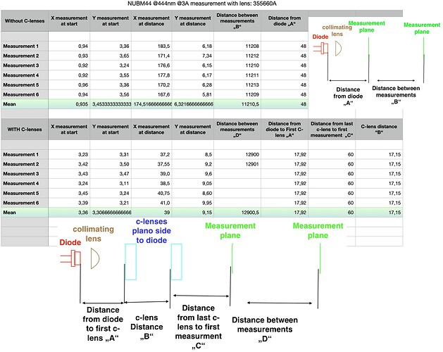
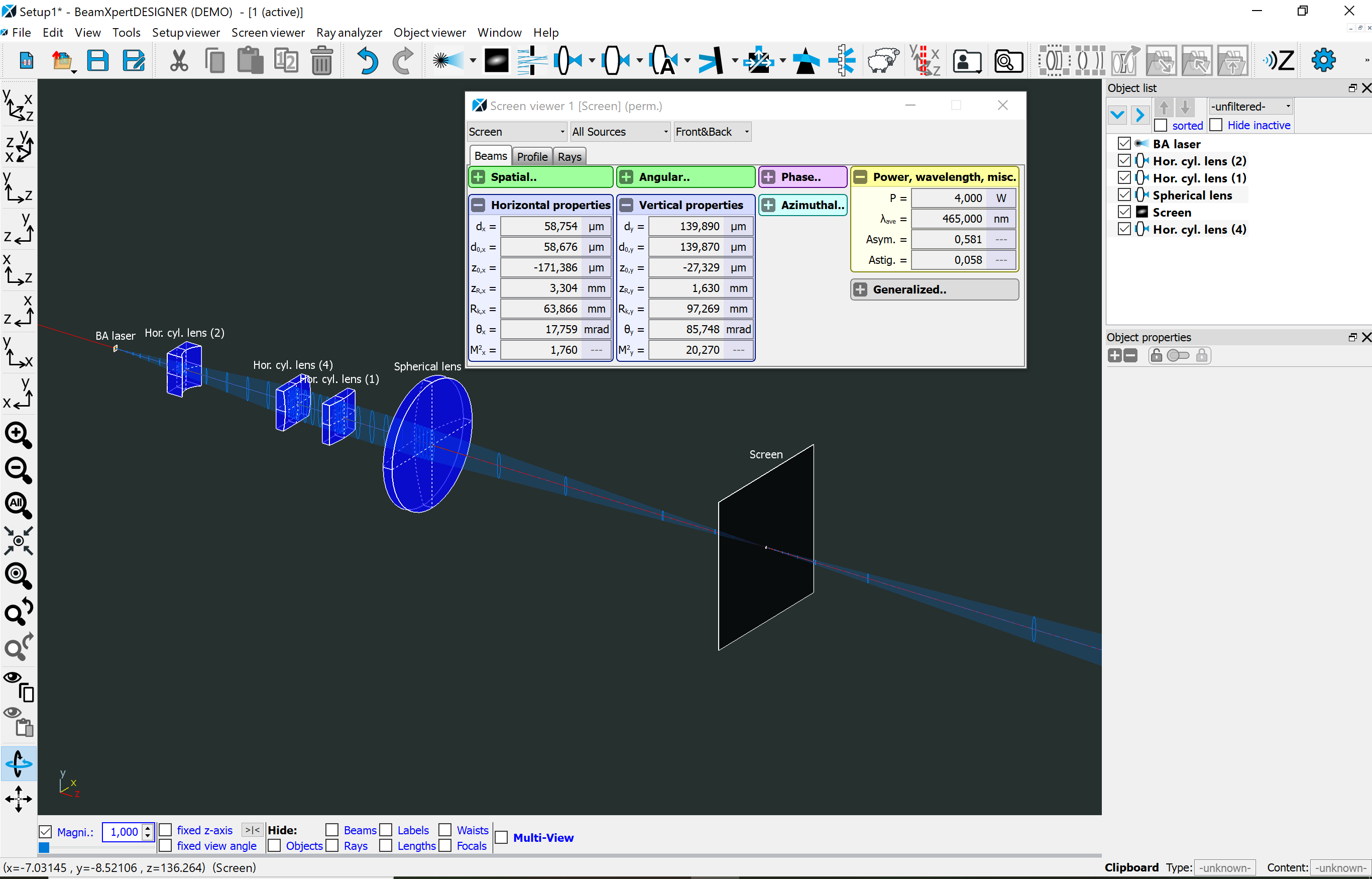
Finally, I simulated the beam propagation using BeamXpert DEMO (thanks builder!!) and tried many combinations of the lenses that Phillip has available until I found a combination that works well enough imo:


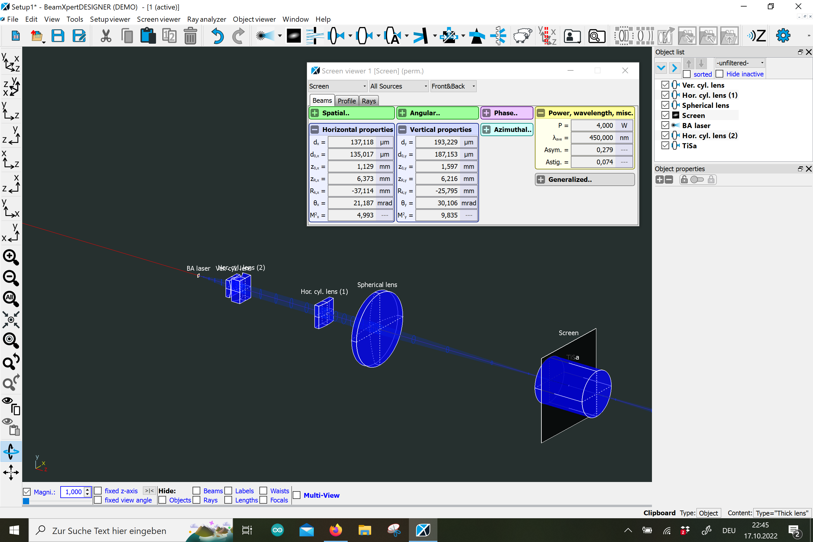
The first lens is used to collimate the vertical axis, the second one expands the horizontal axis and the last one collimates the horizontal axis again. The 2nd lens is not strictly necessary since the horizontal axis (slowly) diverges on its own, but makes the setup a lot more compact. I get a spot diameter of 135x187um and ~6mm rayleigh length in y and x. The spot is much larger than the reported above 10x35um but I was not able to achieve that at all with the lenses available. I would be very happy about tips regarding getting pump waist diameters like those. I am wondering if this is even possible with my diodes.

Anyways, that’d be the planned optical setup for ~10W of pump power. How I do this mechanically is not clear yet, but thats a problem for future me :slight_smile:

If you have any tips or comments about this project, please let me know! As always, I very curious what you think.

Nik

3 Likes

A nice project always gets me interested!

Just some thoughts:
I would recommend finding a different lens arrangement.
Bildschirmfoto 2022-10-18 um 13.07.10
This might work optically but will be very difficult to align and more important, impossible to clean.

If you can, go for at least enough distance between the elements to have them easily cleanable.
I speak from experience here: no matter how clean you work. The lenses will get dirty and will need cleaning.

Aligning is also hard because you dont have space to use real holders and the “glue the optics to a plate” approach is very hard if two elements are close because its too easy to move both elements while adjusting one.

Mechanics:
If you have never seen it, this is the mechanical approach that the chinese take:

If you get the machining right (hight wise), its very very easy to align and very stable.
Just some UV glue and some time is needed.
The knife edge holder used in the picture are not the best but work ok.
Thats the same style kvant uses.

You could also do something like Phillip is doing with his Sparrow modules. No need to purchase his parts, but the general idea is easy to implement in a hobby shop and allows easy rotation and z-shift.

Waist setup:
I am not familiar with TI:Sa.
But just one idea that should work, if the reabsorption losses are low.
Having the waist too small (and therefore the rayleight length too small) would increase energy density.
Having low reabsorption losses and high overall pump absorption could make a too small Rayleigh length a vaiable strategy. Having the waist not in the center but near to the facet of the crystal would ensure higher energy density and therefore maybe lower threshold.
This would essentially the same as having a smaller crystal.
However doping percentage needs to be high enough to absorb enough pump power (and no pump saturation should occur).
Also if the reabsorption is too high, the cavity losses will be to high = no lasing.

1 Like

Ah, I didn’t even think about cleaning the lenses. Yes, that is a issue. But I can just shift the last two lenses a cm or two away from the first lens without anything else changing much.
I will probably also take this route, machining a holder block and then using some UV curing adhesive to fix the lenses. Do you have any advise on which glue to use?

Regarding the waist setup: Ti:Sa does actually have a small absorption peak at 800nm but the value of the absorption can change by an order of magnitude depending on doping [source]. Which I do not know. I also don’t really have the means to measure this accurately. So, I’ll probably stick with my method at first and try the other one as well after that. I suppose, expanding the beam using a two lenser before focussing the beam should work for this, and would not influence the collimation section.

2 Likes

I played around with Norland NOA xxx.

I used glue that was recommended by NASA (dont ask me for the paper, it was a long time ago) to withstand high temperatures and vibrations.

After some try and error, i found that some glues have more expansion / shrinkage but for the use case of gluing the optic flat onto a surface they are all almost equal.

High gap sizes is where low expansion / shrinkage glues shines.

Something low viscosity without filler is nice. The fillers are often small quartz particles.
Therefore filled glue does not creep into the small space with capillary action.

I think Phillip can provide you some glue in hobby quantities. Otherwise you might end up buying so much that it goes bad before you can use it up.
Otherwise Norland stuff is quite cheap (including shipping to europe) at AMStech

For hardening: even exposure isnt really necessary but recommended. Again, needed for high gap sizes but not for this application.
I used some cheap Chinese UV leds (ebay) on a small handheld heatsink.

1 Like

Thanks for tip regarding the glue!

In the meantime I have contacted an author (Peter Moulton) of a few Ti:Sa related papers I’ve read and asked him about the reabsorption losses. Turns out, he actually invented the Ti:Sa laser in 1982! He told me that, since TiSa is a 4-level-system, reabsorption losses can be ignored.

Of course, my crystal is only lightly doped, so pumping a short length would result in low amplification. I might be able to get a smaller, more heavily doped crystal though,… Anyways, I’ll redesign the lens array for lowest possible spot size and good overlap with the mode size. I also need to find out how to calculate the mode size for my setup. :'D There’s a lot to do :slight_smile:

Nik

2 Likes

I wasn’t completely sure about that idea. Nice to see that this is actually viable.

Very interesting, speaking to the author and inventor of the Ti:Sa! Very nice indeed!
I am sure you got very interesting informations and a nice talk!

1 Like

Even though our contact was only via email I am very happy to know that this scheme works in general. I have now redesigned the pump system and am getting around 85x95um spot size at reduced rayleigh lengths. The calculated mode diameter is ~50x50um (calculated through ReZonator 2.0, see pic) so the overlap is not extremely good but the spots are roughly similar. Of course the rayleigh length of the mode volume is much bigger problably since its M^2 is around 1.
Anyways, with the lenses available to me, I can’t really do much better, but I have simulated a Galilean beam expander that would drive the spot below 50um (rayleigh length 0.5mm…) which might be useful if the laser actually works and modelocking becomes a realistic goal.
Actually, all of these values (except mode volume) should be taken with a grain of salt since I don’t exactly know the emitter size of the diodes, which greatly impacts M^2.

Also, I found that 4W 465nm diodes are available on eBay. They cost more but they might give a significant increase in absorption, possibly ~25% more than 455nm. I am still unsure if that might be worth the extra cost.

So, I think, I’ll get around ordering all the optics soon and start on the mechanical setup.

Nik


1 Like

very nice work!

I wish you luck and hope you get this beast to lase.

Where did you get the emitter sizes from?
As far as i know no real data is available other than some rumors. (at least for blue nichia diodes)

Also: if you want to use FAC corrected diodes, your simulations dont include the FAC right?
Did you just estimate based on M2 and divergence?

Thank you! I got the emitter size for a typical high power 450nm diode from here. Not an official source but seems to be realiable enough for some ballpark numbers at least.
The FAC impacted divergences are 1x14°, taken from here. Again, ballpark numbers I guess. I suppose through the FAC the emitter size in the simulation should change (probable decrease) but I don’t have any numbers on that…

1 Like

I am just wondering if thats really correct.
Because your M2 seems too low and too high at the same time.

One axis should be single mode and therefore close to 1. I found values of around M² = 2 for the NUBM44 for the fast axis and around M² = 20 for the slow axis.
source

You got 7x14 which is quite different.

The slow axis (M²=14) might be true for FAC corrected diodes without a collimating lens.
But the fast axis should be way better than 7.

I also found M²=20x2 to be somewhat right. I can measure M2 but i can measure divergence of a collimated beam and its size.
That also gave me around M²=2x20

1 Like

Ah, that’s true. The problem is that I really don’t have any M2 values on FAC diodes, just the divergence from the “datasheet”. I was not able to find any info on that, which I find odd. Not even on LPF.

Putting 2x20 (or even 2x14) into BeamXpert really messes up my design so I probably will have to actually measure the diodes before being able to design the optical train.

M² should be around the same as on non FAC diodes. If any, a little better. (At least the collimated beam is better on the slow axis!)
The emitter is the same after all. However, the FAC seem to improve the behavior of the slow axis.

I think thats the case because the collimating lens normally used can only focus one axis to infinity and isnt the right aspheric profile to be optimal for both axis.

Most of the time the collimation is set up to be perfect for the fast axis and the slow axis is expanded by c-lenses. This takes care of the astigmatism but does not correct the wrong slow axis collimation by the collimation lens.

Having the diode FACed will make it possible to treat each axis separately with no added aberration of the wrongly formed collimating lens.

I measured the NUBM44 without FAC. But i dont think that this data would help you?

I also just noticed that you have the curved surface of the negative c-lens oriented to the diode. That works but lacks something:
Both the expanding and focusing c-lens will add spherical aberrations. It seems like that they get canceled out if the negative lens is oriented differently.
Have a look at the picture of the Chinese module.

I am not sure on why thats the case, i got empirical proof that its really better this way.

1 Like

I’ve thought a bit about it and think the data might be helpful to me. The M² shouldn’t change through FACing (as you said) and the NUBM44 and my 4W FAC diodes are in a very similar power class so they probably have a similar emitter size.

Thanks about the heads up regarding the c lens. I’ll turn it around!

These are my measurements for a non FACed NUBM44 diode.
Yes its quite crude, but the important stuff should be clear.

Keep in mind that the 1,5w/1W green diode is quite different. Its much better in beam spec if collimated to infinity so M² must be way better.
9a529b81a48efcd4f105e7ec9ad08e9bb0787796_2_629x500

1 Like

Hi all,

I have now finally received the FAC 465nm diodes and measured them. M² is indeed near 2x20, my values are 1,76x20,27. The divergence is 0,6°x9,6°. This is better than the datasheet suggests (at least for the 0,6°, min is 0,9° in the datasheet; 9,6° is within spec), but it really repends on how you measure it, aka what you count as the “outer diameter” of the beam. I used the core “bar”, which contains most of the laser power.
Anyways, this is, as builder suggested, definitely different from what I assumed before, so I redesigned the pump setup again:

I now get 58x139um² for the pump beam spot. With the calculated mode diameter, this means about 30% pump-mode overlap at best which is okay-ish but the best I can do for now. I’ll compensate that with 2x4W(465nm)+1x1W(520nm)=9W of pump power :wink: I’ll order the optics very soon.

Even better news: I was able to order a 2,4mm long brewster cut crystal with FOM >150 from Optogama for much cheaper than usual because they had one left from a previous order. With this crystal I am fairly confident that my setup can far surpass the laser threshold even with 5% outcoupling, although I dont want to jinx it :slight_smile:
Now I have to design the pump module, which I want to be a closed off box with TEC cooling. No dust, no problem.

The heatload is as follows:
465nm Diodes: 3A x 4,8V=15W -4W optical= 11W (x2)
520nm Diode : 1,5A x 4,6V=7W -1W optical= 6W
So in sum about 30W at the worst (the electrical specs are all the max from the datasheets + rounding up in very step)
I’d aim for diode case temperatures around 35°C max.
So not as bad as the NdYag, but still, not completely trivial. I’ll design the pump module whilst the optics and crystal are on their way.

~Nik

3 Likes

Hey Nik!
Nice to see you progress.

I would recommend to calculate with a little more power for the green diode (likely a NDG7475 if 520nm).
I know that these diodes get driven at 2A to get over 1W of output, they should last very long at 2A.

As you got many optics, you will have losses that likely reduce your pump power by 10% or more.
Having the additional headroom of being able to drive the diode harder can push you over the edge.

I just want to mention that you could also use the 525nm diodes (if the wavelength is still ok) which are available with 1,5W output power.

The blue ones are Likely NUBM07 (3W) or NUBM0C (4,5W) diodes harvested and backfilled with inert gas. Just to let you know if you didn’t already.

You are right, its probably better to go with 40W, just to be safe.
I actually already have the green diode (indeed a NDG7475), I picked it because it has a better beam quality than the NUGM types. I didn’t plan to overdrive the NDG7475 but now that you say it I think I read a paper in which they pushed them to 1.5W with no issues apparently.

I also didn’t plan to overdrive the blue diodes since I can definitely live with the ~10% loss of power. In this paper, they had a very similar setup with similar OC (even 1% more than me) and crystal length. Their worst threshold was 1.7W with 450nm. Given that I have at least four times that (+15nm closer to absorption peak) with another watt of green (their worst threshold for 520nm was 900mW) I should be able to threshold the laser without overdriving anything. Given of course that I actually manage to align the resonator :smiley:

Thanks for the heads up on the diode type. Its crazy how much the FAC increases focusability. I was able to burn white paper with like 170mA from 10s of cm away during testing. Absolutely insane. I suppose the pump module would make for a really good engraving module as well…

1 Like

Hi all,

I have now finished building the pump module. I ordered the optics from Phillip at Live Lasersystems for a very reasonable price and assembled everything this weekend. I chose a 110 W Peltier for cooling the module and the same circuit (+ very similar code) for driving it as for the DPSS Nd:YAG. Originally I wanted to have all the drivers in the module but then changed my mind because they add quite a bit to the heatload, so the pics below are a mix of those solutions.

Here’s the setup:


The left diode (FAC line, 465nm, 4W) is shaped and then goes through a lambda/2 rotator. It is then combined with another shaped FAC diode via polarization cube. Finally, the green diode (shaped via prisms, I had them on hand) is added using a dichroic mirror. All the optics are pretty low loss, I can’t imagine that I am losing more than 1W overall. Here’s a shot with all diodes on, all are slightly above threshhold.

Even at this low power the spot is very bright, though you cant see it in this pic. The optics are glued into place using some UV curing adhesive that Phillip has also sent me (kindly, along with some UV LEDs!)

Aligning the optics took me about 2-3 hours. I made sure that the beams are exactly above each other by looking at the spots (with goggles!) directly after the cube (dichroic mirror for the green LD) and at a screen about 3m away. Only when the spots are on top of each other at both positions are they truly aligned. This whole job was quite fiddly but I really like this kind of fine stuff :slight_smile:
Anyway, the beam is finally passed through an AR window. After cleaning, aligning and glueing everything in place, the module is closed off from the environment, so that no dust may enter.
The module is flipped so the heatsink is on top. That way the beam is closer to the table and it also allows better airflow for the heatsink. The fan in the following pics/vids is temporary by the way, two better fitting fans are on their way :smiley:

So, thats it! The module emits this beautiful (yet very hazardous) light blue/cyan beam. Each diode can be switched off/on separately. On the very left is my driver/powersupply combo (yes poor cable management). The PCB has two LEDs for overtemp and sensor issue indication. However, until now, the diodes have not surpassed 40C (target is 35 and overtemp is 45) even when switched on for quite long.
Here’s a video of the module running
And here I switch on the LDs sequentially.

The beam is absolutely powerful enough to be visible through rayleigh scattering.
Engraving would be absolutely no issue with this beast

Of course, laser goggles are absolutely mandatory. So, thats about it for the pump module! Now its time for me to get the resonator going! The crystal has already arrived.


I got this crystal from Optogama for quite cheap since they had one left from a previous order. Looks really good!
It is pretty small so I assume that cooling it will probably be necessary… At the very least passively with a heatsink, TiSa is supposed to be relatively resistant to heat though. And since it is brewster cut, there’s no coating to be damaged.

Thanks again to Phillip for helping me in this project! I’ll get to the resonator in the next few days.

2 Likes

Nice Work!

I am quite surprised that you got the PBS and dichroic aligned by hand and just using glue to hold it in place!
I did countless tests on that approach myself and could never get that to work reliably!!

I tried combining 3 diodes (RGB) in the smallest package possible.
I needed longer distances (laser projector application), so I am not sure if you are very very very skilled with stable hands or you are just lucky or if your shorter distances made it so much easier?

Thank you!

Yeah, I dreaded that task as well but in the end it worked out better than I thought. Though I am not experienced at all, I do have pretty stable hands. But I suppose the bigger factor are the shorter distances. 3 m is pretty long but nothing when compared to projection distances… But good enough for my case. Even at 3m it was quite fiddly.

1 Like