Powerful DPSS SHG Nd:YAG Laser build

Thanks for the tips!

I have now measured the heatsink. The setup is as follows: I’ve got a 470 Ohm power resistor tightly screwed onto the spot where the TEC would be and a thermocouple about 3cm away from it. I then put 220V across it (yes, much danger), which should be 103W of power going into the module. Then I let it heat up for ~1h with the heatsink fans running (normal operation) and it stabilized at 37°C, with 16°C being ambient. So, Rth = (37-16)/103=0,2K/W which is smack on what the manufacturer of the similar heatsink says.
Here’s the setup:

The following pic gives a hint on how big this heat sink is.

Now, with 0,2K/W, Qc = 50W + ~30W and T_ambient = 30°C I get T_hot = 47°C, thus dT=22°C, which my TEC needs 5A (7V) for. COP is 1,5 so pretty good. That leaves some headroom for power dissipation by the drivers. At my usual 20°C ambient COP is about 2,2!

So, finally some good news :slight_smile: Now I need to wait for the TEC to arrive and redesign the clamping arrangement for the diode module.

1 Like

Thats perfect!
Your setup should now be ready to run long duty cycles.
Nice work.

Now you need a tec driver with PID control. Its simple to implement with an arduino. (keep D at 0 first)

on a site note:
I actually had one of these resistors explode on me while testing heatsinks like that. Also 230V and also one of these resistors but the 50W variant.

They violently explode if overdriven/overheated. Both ends shot out of the metal body sending the sand filling all over the place.
The 230V wire touched something and shorted out blowing the fuse.

I didnt even know what happened at first because i wasnt looking at the setup.

BTW: you got your grid voltage wrong. Its 230V in Germany. So your setup should be closer to 112W dissipation.

Thanks :slight_smile:

Yes, I’ll work on the firmware now. The Arduino PID library (Brett Beauregard) should work fine for that. Do you have an idea in what region Kp and Ki should roughly be?
Regarding the TEC driver, I looked up my notes and it is a simple buck converter designed to run at 6 A and a switching frequency of 25kHz. The 100uF cap is already on the board so it should run fine. The 50uF inductor can handle 10A.

That story regarding the resistor is quite scary. I guess I am lucky that nothing happened, although I did run it at its rated heat load of 100W. I don’t like working with line voltage like that but I was what I had available.

Yes, 230V. Makes my calculations even more favorable :smiley:

I don’t use library’s. (for simple PIDs - for more advanced stuff, i do!)

Thought experiment:
Just looking at a fixed P value of 5:

If you have say 8 bit output resolution (256 max), and 1k resolution on the input.
You will get a pwm value of 5 for 1k setpoint deviation. Which is around 2% output power.

If you got 12 bit output resolution (4096 max) with 1k input resolution. The same 1k deviation would get you will only get 0,12% output power!

So P values heavily depend on input and output resolution. The I and D term is even worse, it also depends on the timing of the pid loop.

Make sure to use as much input and output resolution as can get.
For example: you could read the voltage of a NTC with 12 bit and calculate the temperature in C with 0,1C resolution.
It would be easy to use the 0,1C resolution variable to calculate the PID but it will result in lower resolution and therefore worse loop stability.

PID should be without discrete steps.

Do you plan to design your stepdown with only the Arduino? Thats a heavy challenge in itself!

10uH + 100uF output filter will result in heavy voltage ripple at 25khz.
(And your small caps likely can’t handle the rms current)

A quick simulation looks like that:


problems:

First of all: layout!
Make sure you get the Layout right. Get rid of big current loop areas otherwise noise will be a problem.
Make the high current traces as short as possible.
Make sure your fet/bjt gets driven hard enough.

Having no current feedback will make your design not very robust.

A soft-start is necessary to reduce the startup current.

A single programming error that leaves the fet on for too long will kill it.

I would go a different route, or at least choose different part values.

What’s the circuit you got so far?

The explosion looks like this:

The vaporized copper is clearly visible.

That exploded resistor is scary. R10 resistor, so 5290W at 230V… Is that right?

I really thought this was not going to be the difficult part of this project :grin: My plan was to get a 25kHz pwm signal from the Arduino which I read somewhere is possible and change the PWM duty cycle for voltage adjustment: 0% duty cycle, 0V, 100% duty cycle, 12V. Then use a PID library (neither an electrical nor a software engineer :wink: ) to control the manipulated variable of the PID loop (the duty cycle) to get to my temperature. I planned to use the arduino nano with no adc for this but the output resolution (8 bit) and input resolution (10 bit) are pretty poor indeed so upgrading that would be a possibility.

Anyways, my circuit does actually use a 50uH inductor instead of a 10uH one. I got the circuit from this thread here. I replaced the schottky diode with a regular silicon diode which I am only now realizing might have been a mistake. Also, I paid pretty much no attention to layout, so I’ll have to remake the circuit. No current feedback is not good but I do have the temperature feedback, thats good enough for me at this point. How would I implement a softstart?
I dont think leaving on my mosfet will kill it, its an IRF1405 with sufficient heatsinking for >10A. Also, I wasn’t able to find a capacitor able to handle the 6A rms current (if it is indeed 6A) on my usual supplier (reichelt), where would find such a cap?

Sorry for the many questions, as you can see, my knowledge in electronics is quite limited.

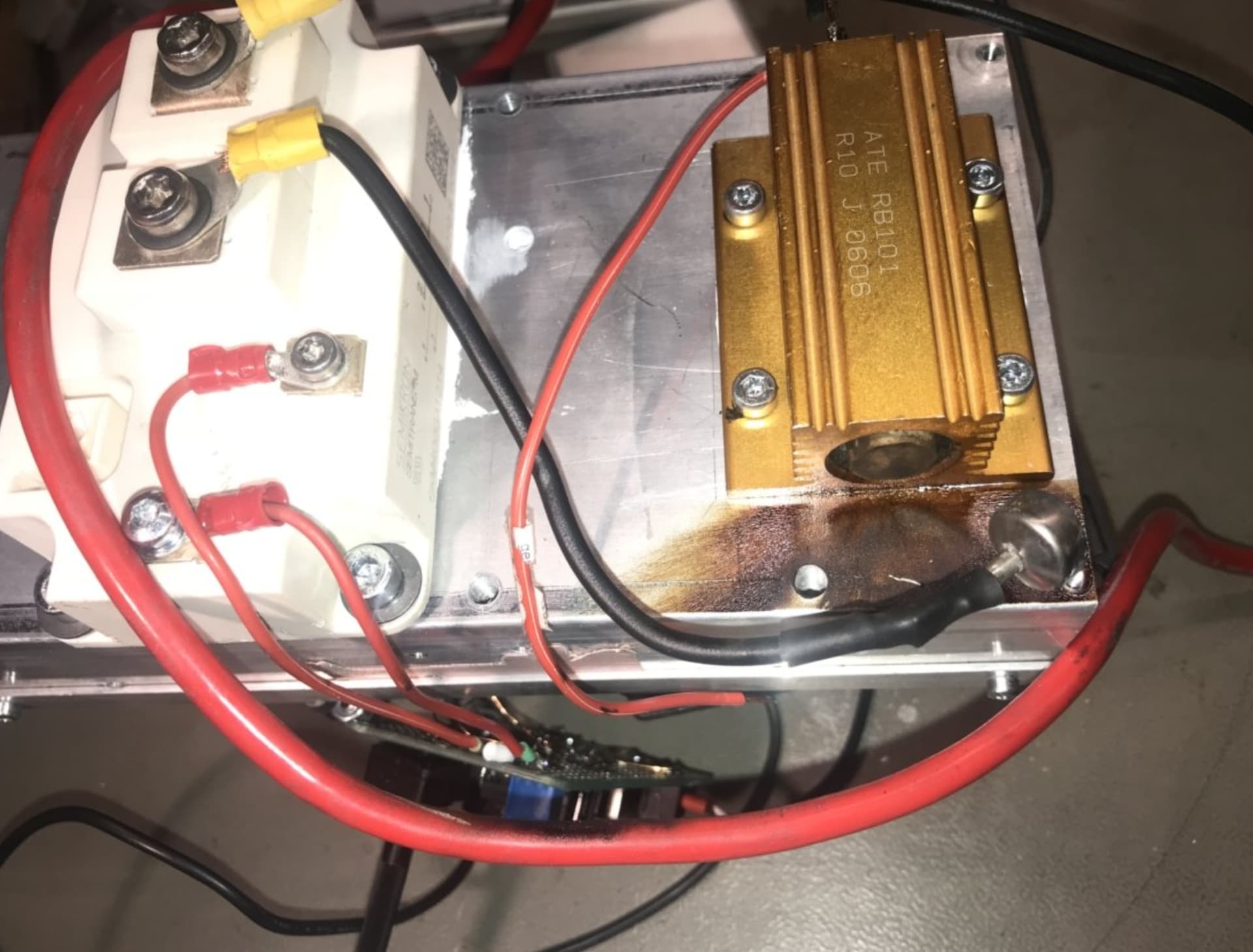
I just got the picture from someone that killed one of these resistors yesterday while working on a dc/dc converter for a solar to battery storage / grid solution.
Just an example to show that its not that uncommon :smiley:

Everybody needs to start somewhere.
I am also no software developer. So i imagine my code would be scary to everyone doing serious stuff.
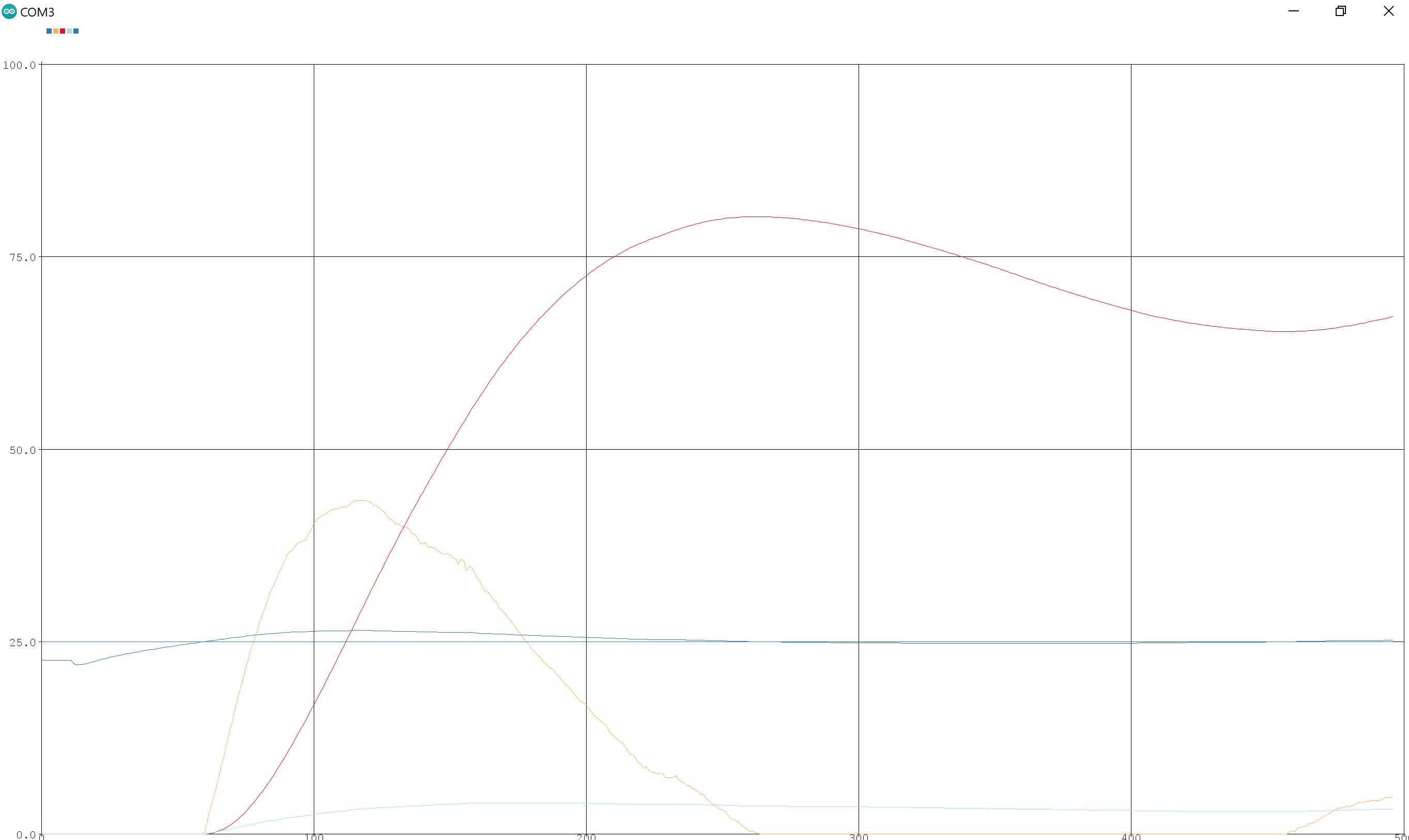
But thats a simple PID loop for a fogger i build:

void PIDpump(){            //this gets called by ADC_measure which gets called by timer. Repeatable intervall for PID loop

  //BackEMF -> value of motor speed 0-900
  //requestedFog -> 0-700 needed motor speed.  
  //OCR1B -> output stuff 0-2500 "pwm value" lowest value 250, highest value 2075

if(requestedFog >= 1){                 // we need to start fogging, calculate PID

  error = requestedFog - BackEMF;            //calculate velocity error term reqFog is set point while BackEMF is current value

  cumError += error;                         //I term, gets integrated by adding 

  if(cumError >= 500){                       // wind up correction   
  cumError = 500;                            // I term, set to min
  }
  if(cumError <= -500){                      // wind up correction   
  cumError = -500;                           // I term, set to min
  }
  
  outputValue = (Kp * error) + (Ki * cumError) + (Kd * (error - lastError));       //calculate output


  if(outputValue > 2075){                                                    // limit output to max and minimum PWM value
     outputValue = 2075;
  }else if(outputValue < 270){
     outputValue = 270;
  }

  lastError = error;                         // safe last error value for D calculation
  OCR1B = outputValue;                       // write PWM value to register

}else{                                              //we dont need to make fog -> stop PID and reset
  OCR1B = 0;                                        //write 0 to PWM register
  error = 0;                                        //error 0
  lastError = 0;                                    //last error 0
  cumError = 0;                                     //integrated error 0
  }
}

The real PID stuff is essentially just these lines:

  error = requestedFog - BackEMF;            //calculate velocity error term reqFog is set point while BackEMF is current value
  cumError += error;                         //I term, gets integrated by adding 
  outputValue = (Kp * error) + (Ki * cumError) + (Kd * (error - lastError));       //calculate output
  lastError = error;                         // safe last error value for D calculation

First the error gets calculated by just getting the difference between set point and current value.
This error term gets added each time the PID loop runs. Thats for the I term. We essentially integrate the error over time.
The output value gets calculate by just adding all the PID components.
Lastly the current error gets saved to calculate the D term at the next run.

Very simple, so no real need for a library.
My loop includes switching the PID off and having wind up correction for the integrated error, otherwise high integrated values would lead to oscillations.

Softstart could be implemented by increasing the PWM duty at startup from 0 to the PID output value slowly.
I would also limit the maximum duty-cycle to make the tec always run with its optimum COP.
No need to supply it 12V if it will have enough power at 7V.
Running it at 12V at startup would increase losses and make a bigger power supply necessary.

Stepdown:
I thought i read somewhere that you used a 10uH inductor, my bad.
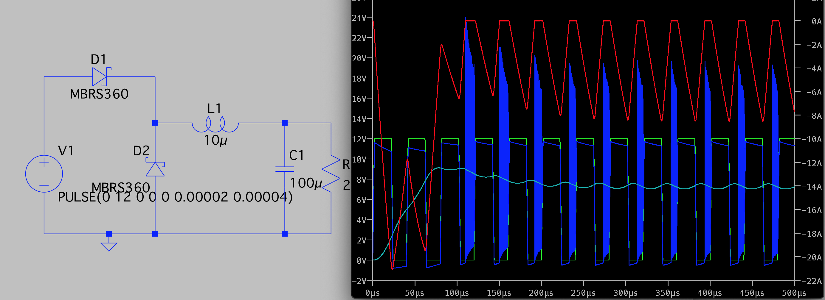
Your assumption of controlling the voltage by duty cycle is correct if your inductor is big enough to have no zero current times. With 50uH and your load, that works out perfectly.
The circuit is actually essentially a stepdown regulator with common positive. The simulation i posted is the same but common negative.
That circuit is nice because you can get away with a n-ch fet (better parameters) and can use a simple ground related control signal (0-5V for example) but pay for it by having no ground reference on your load. But thats completely fine here.

YES! Sorry! Completely true, i messed up and somehow thought about step up which essentially shorts the power supply with the fet.
You just need to make sure that your fet can handle the max current and max voltage and max power dissipation. It also needs to be completely on. That could be a problem here.

U and I should be clear, your fet is rated for more then enough. But your nano will only output 5V to control your fet. Your fet is barely on enough. You will get around 40mR at 5V instead of the 5mR at 10V.
So your efficiency will not be great, at 10A you are looking at around 4W of losses.
Not great not terrible.

Your diode needs to be fast. You will get losses because of the higher forward voltage. The diode takes the current while the fet isnt, so it needs to carry the full load current.

Because you got a much bigger inductor, your current never gets to zero. Therefore the load current is always shared by the capacitor and inductor. You will not need a 6A capable capacitor. Around 0.75A RMS should be enough.
You load would still receive around 100mV of ripple which is quite much for a power supply but it should be ok for a tec.

But you also need an input cap. The peak current to “charge” the inductor needs to be supplied fast, caps will do that.
I just borrowed a picture: (common ground - q1 would be your fet with q2 being the diode)
4846.Figure 1 Buck Current Loops.png-550x0
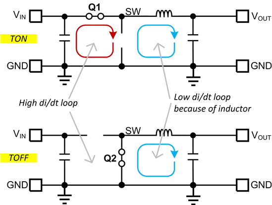
The blue and the red loop needs to be small otherwise noise will be radiated.
If you got no input capacitor, the high di/dt loop will be huge, extending to your power supply.
You need the input cap to keep the loop small and supply the high peak currents with local capacitance.

1 Like

Hi all,

today has been very productive :slight_smile: For the last few days I have been remaking the TEC driver and the corresponding code which are now finished and mostly tested.
The driver circuit works great, I can use the PWM signal to linearly scale the voltage (and thus current) without problems. I have also added an ads1115 16-Bit ADC to measure all the temperatures more accurately. The PWM on the Arduino is realized through the Fast PWM mode of Timer 1 from the Atmega328 chip. Since I need 20kHz and the chip frequency is 16MHz, I get a 16MHz/20kHz= 800 step PWM signal at Prescaler=1. Since I limit the voltage at 8,25V (7A at dT=20°C), I get 550 effective steps, not much but at least double the resolution of standard analogWrite. Understanding this whole timer thing took me a bit, but it works as intended now (Credit really belongs to this german blog).

It is really awesome to see the PWM duty cycle change on the oscilloscope whilst the PID-algorithm does its thing! This whole part of the project really has been a learning experience.


Meanwhile, during PID tuning I used the serial plotter to plot some plot values. Its not perfectly tuned yet, aka could probably be way faster, but it definitely works as it should!

Here, blue is the diode temperature, green is the P part of the PID equation, red is the I and light blue is the TEC voltage. Note that P and I are scaled so that everything fits on the screen, so ignore their amplitude. The temperature definitely approaches 25°C over time.

So, I still need to do some long time tests and fine-tune the PID coefficients but cooling should no longer be an issue :slight_smile: Thanks again builder for your help and patience.

Now I’ll rebuild the resonator and optimize it. Remember that I am not reaching my goal regarding output power, so to rule out my “crooked” KTP I ordered a 5mm long one from Optogama. Maybe that helps. I could also “sweep” the diode temperatures to find the exact temperatur optimum for the diode.

~Nik

2 Likes

Nice to see you progress!
Love that!

Tuning the PID loop is a story for itself, it’s a always some sort of compromise.

Good work on getting the times to work on the atmega. Just using the analogwrite arduino „api“ is very limiting. If you get into better uCs or more advanced PWM outputs, you absolutely need to use the raw timer registers.

Short update, the KTP from Optogama has arrived and has roughly doubled the output power! Maybe because it is longer (5mm instead of 3,5mm) or the quality of the crystal + coatings are better or both. I got the KTP for 75€, which I think is very reasonable. Of course I managed to instantly chip a huge chunk off one face, about half of the area is gone… :frowning: But, the other half remains and is operational.

I have noticed another issue, which might actually be the (or a) key problem for my limited output power: The driver delivers only about 23A instead of the 30A that I am expecting. Since SHG efficiency goes up quadratically with increasing input power, the remaining 7A might actually add a lot. I’ll review my driver once I get around to doing that… But currently, the TiSa is priority number one :slight_smile:

2 Likes

I feel you crystal mishap…
Wo gehobelt wird fallen späne :smiley:

Getting 2x output is really a big achievement!

Interesting on your driver problem!
So your initial tec must be even worse than we where expecting!
After all, the power dissipation of your diode was less than anticipated.

1 Like