Yep i would think the same, i just dont want to hijack your thread (without permission) about a laser and talk about tec specific stuff.
I think this will be a long post.
Lets start at the basics on how to use a tec (you did most of that right but others might need a bit of help):
-
Thermal stuff works the same as electrical stuff, there are resistances (thermal resistance), current (heat flow) and voltage (temperature differential). If you have basic understanding of electronics, thermal stuff is easy.
-
Tecs are very fragile, they break easily because there base material is a ceramic substrate. Make sure to have both surfaces that connect to it flat without big milling marks. Ra should be below 1,6.
-
Use a thermal interface material. Small voids from surface irregularities would lead to the tec
-
The Tec needs to have good contact on its whole surface. The Tec base material is a good conductor but if the Tec isnt contacted on the whole surface you get parts that dont contribute to the heat pumping action which lowers the performance.
-
Keep thermal shorts as high resistance as possible. The tec needs to be mounted in some way. This most of the time means clamping (using bolts) it between surfaces. Doing that will create a bridge between hot and cold side with a defined thermal resistance. The resistance is responsible for how much energy is flowing from hot to cold. Having long bolts with low thermal conductivity and insulation washers is key to keeping that resistance high. So stainless steel bolts and plastic insulation washers.
-
A Tecs is more efficient if its temperature differential is low and its overall temperature is high.
Getting 10K differential from -80°C to -90°C needs way more power than getting the 10K from 60°C to 50°C.
Keep that in mind while looking at the graphs on your tec data sheet. Most of them have curves for 50°C hot side temperature and for 27°C hot side temperature.
Your calculation for the dissipated power of the diode is perfectly correct. However as we are doing a “back of the napkin” / “ballpark” calculation, i would rather be a little pessimistic than optimistic.
I would take the full 30A*1,7V = 51W instead of subtracting the optical power. You all ready said it: the crystal thats cooled will also absorb some of the optical power and convert it to heat.
You also got additional heat that needs to be pumped because your mounting hardware is essentially a “thermal short” (similar to an electric short) because it connects the hot and cold side of the tec together.
Some amount of power also gets into the cold side because of convection and conduction of the surrounding (hot) ambient air.
Its hard to estimate how much these factors play a role, so i would just go all in and have too much tec power that too little.
So our first fixed value is: we need to pump around 50W
A tec essentially just creates a temperature difference across both surfaces. This difference depends on current and heat load (=pumped thermal power).
So to estimate current usage and choose the tec, we need to know the ambient conditions and the temperature we want to keep our load at.
You said the diode is smack on 808nm at 25°C. So that gives us our fixed cold side temperature of 25°C.
To get the actually differential across the tec, we would need the hot side temperature. However the hot side is connected to a heatsink which isnt fixed in temperature. The heatsink temperature depends on the thermal load.
A heatsink has a value “thermal resistance” which describes → how much temperature rise it will have at a given dissipate power level.
The value is for example 0,75K/w which means the heatsink would get 1,5K hotter if we put 2W of power into it. The formula is Power * Resistance = Temperature rise.
Your heatsink does not state values and you added fans so its likely not accurate. The value is easily measured. Drop some power into the heatsink and measure the rise above ambient temperature. The resistance is then just: Temperature Rise / Power = Resistance.
So we need the load of the heatsink and the maximum ambient temperature to get the heatsinks temperature. (which is equal to the hot side temperature)
However there is a problem: The load into the heatsink is dependent on the tecs thermal output power on the hot side.
Which itself is dependent on the hot side temperature.
To explain this, I will use a different data sheet of a slightly different tec because its clearer.
Datasheet here
Lets assume for a moment we know that the heatsink will get to say 55°C.
That would mean we need a differential temperature of (55°C-25°C) = 30K across the tecs sides.
With these variables, it would be possible to see how much power the tec needs.
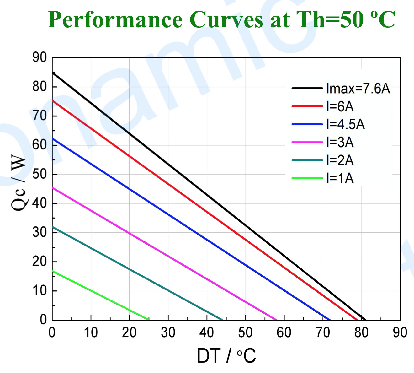
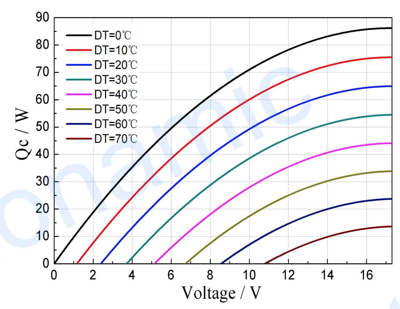
A look into the data sheet lets us use this curve to see if thats even possible with our tec candidate.
We use the Th = 50°C (temperature hot side = 50°C) graph because our imaginary heatsink reaches 55°C which is close enough. Qc is our heat load of the diode (50W) which gives us a estimated drive current at DT=30°C of around 6,8A. The tec is almost fully loaded and cant take much more power.
Scrolling a bit down gives us:
We need just over 12,7V to pump 50W @ DT=30K.
Everything is good so far?
We know our tec needs 12,7V @ 6,8A to pump 50W so our total heat load into the heatsink would be around 87W of power for the tec with an additional 50W of pumped heat = 137W into the heatsink.
NO! our tec is struggling hard and is just barely able to pump the heat which results in very bad performance. Our heatsink needs to be much bigger than necessary with the right tec choice.
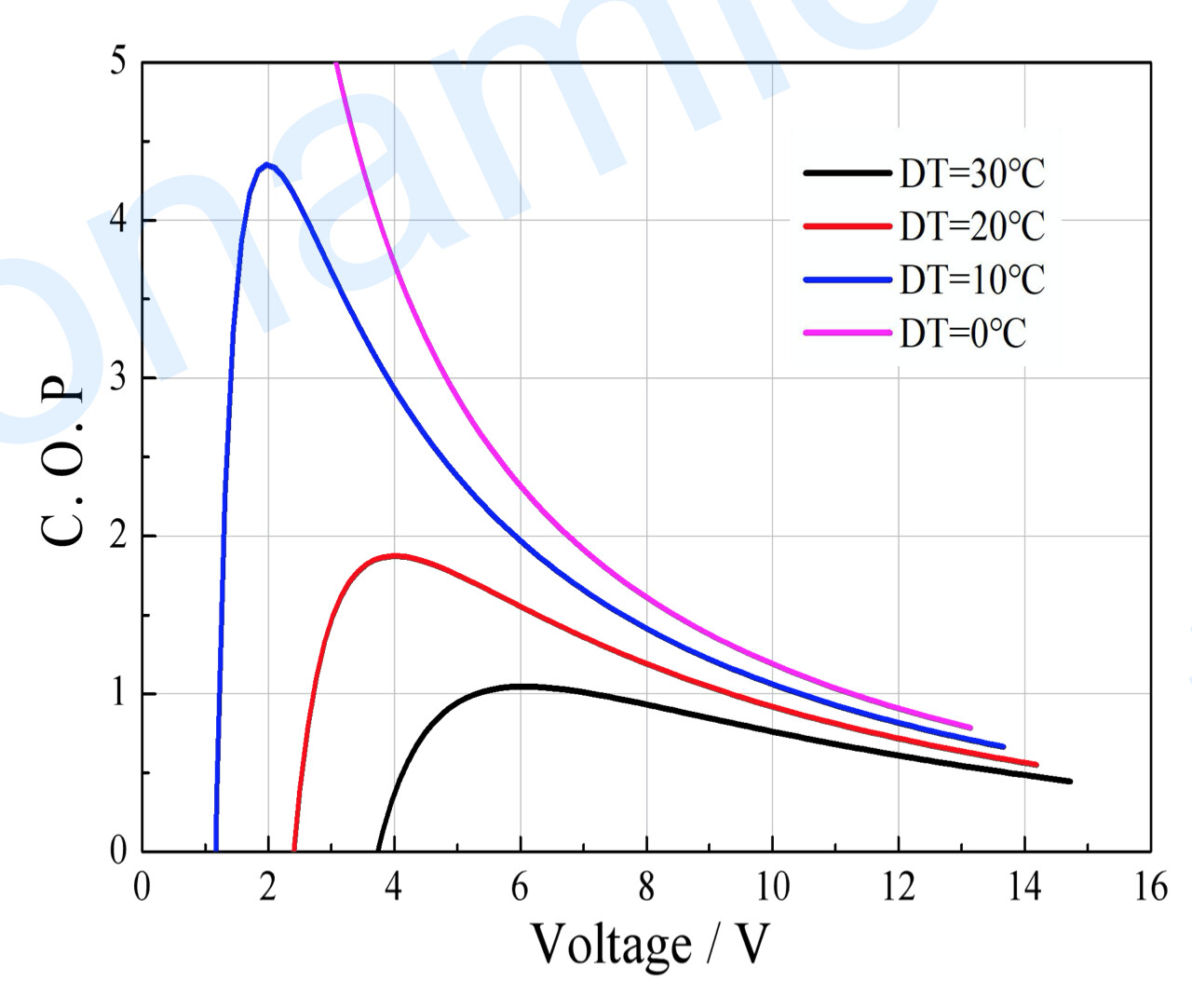
Having a look at the next graph will tell us the whole story:
The COP is a measure of how efficient a heat pump is. having a COP of 2 would mean pumping twice as much heat as electrical power is spent.
The COP on our imaginary setup is around 0.57. So we need to spend around 90W to pump 50W.
The graph shows If we could use the tec at 6V, we would get a COP of over 1, meaning spending 50W to pump 50W.
The next part is a little “gusstimation”.
To make sure we stay inside the maximum efficiency band of a tec, we need to choose it according to our heat load. A good rule of thumb would be around 3x as much Qcmax as we need to pump. This almost always gives us a COP of around 1 for the usual laser applications.
We need to pump 50W → our tec needs to be able to pump >150W.
Lets use a Tec that respects this rule of thumb:
Datasheet
This rule of thumb also makes our hen and egg problem vanish. We can choose the actual heatsink resistance based on our expected heat load.
It would be around twice the power we need to pump. So our heatsink needs to be able to dissipate around 100W without getting hotter than around 60°C.
A heatsink hotter than 60°C would make the tec struggle as its differential would increase and therefore reduce the COP.
If we have a normal indoor device, its expected that is should work in temperatures of up to say 35°C ambient. Some applications require this to be higher, others can get away with lower max temperatures.
If we stick to the 35°C max ambient, our heatsink needs stay below 60°C. This gives us a differential of 25°C for 100W of power or a heatsink with a thermal resistance at or below 0,25K/W.
We can now just use the tables inside the data sheet to see how much voltage and current the new tec will need to keep our load cool.
Reading them would give us around 6A @ 7,25V which gives around 44W of power usage with a chop of over 1.
The heatsink needs to dissipate around 100W which gets us to a resistance of 0,25K/W.
The first that that also could cool the load would use 140W and wasnt able to be run at heatsink temperatures of 60°C. It could only pump 50W at 55°C or below.
So the heatsink would need to be way bigger because the differential was just 20°C @ 140W which is around 0,14W/K, so much much bigger.
Long long text 
If something is unclear, just tell me, its hard to write everything down into a coherent explanation.
On your setup, there are at least two facts that kill the performance of the tec.
You said your tec struggles at just over 30°C heatsink temperature. So its essentially just able to create a differential of 5°C which is very low.
I suspect a bad tec (cracked or a dodgy source) or that your mounting is subpar.
The tec is build out of many thermal couples, each is contributing its own share of pumped power. You tec is a 127 type, meaning it contains 127 pairs of pumping elements. Having the tec surface not covered completely leaves say 10% of the couples with high thermal resistances to your load which makes them run at way higher differential temperatures resulting in much lower heat pumped.
Thats certainly a factor but cant explain just 5k of differential.
The L-type clamp that holds the module onto the tec certainly contributes another 5-10% performance loss because of the thermal short.
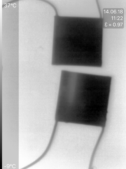
However i think you got a dodgy ebay tec. I seen my fair share of tec from crappy sources, they are cheap but contain non working junctions that waste power and dont pump heat:
(darker = colder ,two tecs on a heatsink)
This thermal picture shows two elements, one good one and a dogdy one.
You can clearly see that the cheap one has a complexly failed row of couples that let heat flow back into the cold side. Something like that is killing performance.
(grammar and typing mistakes for your pleasure, i dont want to go over this again - i am not a native speaker)
Way to long but i struggle to boil it down further.