Before we even begin this tutorial, I want to take a second to mention that this is not an overly simple project and does require some effort and desire to complete it. If you have no experience with soldering and assembling electronic devices and can’t handle the requirement of patience, this project is probably not for you. If, on the other hand, you’re interested in attempting to figure out the basics of how a laser show DAC works by assembling one, read on! Myself and others are often here to answer questions.
UPDATE: Tutuorial has been updated with a complete wiring diagram and detailed tuning instructions from DrLava himself!
EDIT: drlava is presently sold out of fully built correction amp kits, but you can still buy bare boards from him. Links to obtain all the necessary parts for the drlava correction amp can be found here, with an even more updated version here. If you want a full kit, assembled or unassembled, you can get them from 300EVIL here: USB SoundCard DAC Amp Correction Kits - By AUDIOLASE These kits are a tad more expensive, but they include a very good 12V dc-dc converter (results in a larger scanned image) and a built in DB-25 connector. I highly recommend them. Wiring the 300EVIL amp is actually a bit easier than the drlava amp kits since the DB-25 output connector is already installed. All you need to do when using these is wire the connections between the soundcard and the amp.
I’ve tried to include everything necessary for construction of a soundcard DAC here in this tutorial. Many thanks to Drlava for his help and input. Hopefully someone finds this useful! Also, special thanks to Dean Hammonds for the original correction amp design.
This system is typically used with LFI Player show software and HE Laserscan as the free options, but there is other software available for sound card DACs at cost to the user. These are available online for download:
LFI laser player: LFI Player 3D Laser Display Software download | SourceForge.net
HE Laserscan: http://www.he-laserscan.de/include.php?path=content/overview.php&catid=1&type=4
This tutorial assumes you already are familiar with soldering electronic components and very basic electronic theory and are comfortable building DIY kits. It also assumes you are aware of how to set up and install drivers for a computer USB sound card.
The most commonly used sound card for this setup is this cmedia sound card card from DX. (the correction amp can be purchased here or here) The only other tutorial that talks about a sound card DAC on this forum uses the previous revision of this card. The most recent revision has slightly different connections, since it is an 8 channel card as opposed to 6 channels for the previous revision. Due to issues with buggy Vista drivers, I don’t recommend using this sound card with any OS other than Windows XP 32bit or Linux. Any other sound card can be used as long as you feel comfortable finding the proper channel output capacitors to connect to on whatever card you might use.
For the DAC setup, we’ll only be using the first 6 channels. You’ll end up with the correction amp outputs connected to your laser modulation (up to three for RGB) and your galvo amps (to control X,Y movement). The 6th channel is for “Intensity” but that is not used with today’s solid-state RGB projectors.
The connections must be made on the positive side of each output capacitor so that we get a DC signal (you can see exactly where to connect in the closeup photo below).
In the following image, on the sound card, the connection points are as follows:
Blue wire = L Front channel
White wire = R Front
Yellow wire = L Rear
Red wire = R Rear
Black wire = Center
Orange Wire = Subwoofer
On the correction amp board there is a row of input pins. The first two pins are labeled 5V and Ground, and the last pin is also labeled Ground. Both these ground connections must be connected to ground for the correction amp to work. The middle G is a redundant ground pin on the correction amp, so it needs no connection. On the USB sound card board are some solder points right behind the USB connector that can be used to supply power to the correction amp.
The power connections to the correction amp are as follows:
Red wire = 5V (pad furthest to the left)
White and Black wires = Gnd. (both pads furthest to the right)
The connections can be seen in this image:
The defaults in most software are as follows:
Soundcard channels | Scanner function | Soundcard Pin in Picture Below (looking from left to right… you can also see my channel labels written on the card)
Left | X galvo | 1
Right | Y galvo | 2
Left Rear | Red Laser Modulation | 3
Right Rear | Green Modulation | 4
Center | Blue Modulation | 5
Subwoofer | Intensity | 6
Here’s a complete wiring diagram:
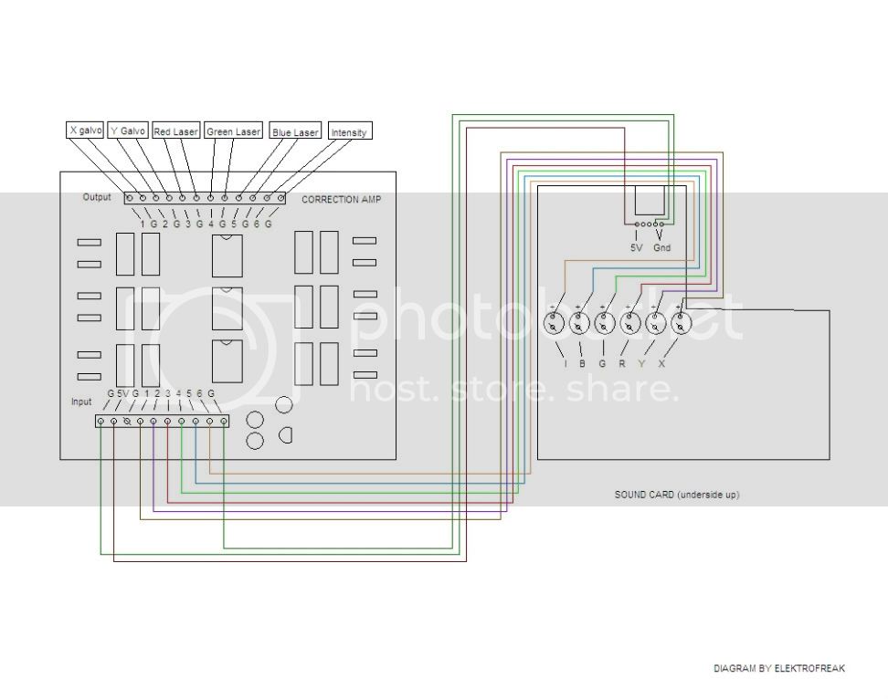
You have to go into the settings for the sound card (which you access through the little white and blue icon in the system tray in the case of this specific card) and set it to 6ch. By default it is set to stereo 2ch, which will not work. 2ch does not allow for your modulation channels, and using the DAC in 2ch mode will make it impossible to tune.
NEW!!
Here’s tuning instructions direct from drlava himself:
Tuning the sound card DAC correction amp:
Tuning the amp is simpler than it looks. There are 6 channels, but only two adjustments per channel, and each channel is adjusted the same way. Tuning only needs to be done once after construction of the audio card DAC.
First, a note of caution: Never plug in or unplug the USB sound card while your projector is on and connected to the DAC. Doing so will cause the sound card DAC to produce out-of-spec voltages that may cause dangerous beams to shoot out of your projector.
Tuning the sound card DAC. Needed: multimeter, small flathead screwdriver, max.wav, wires.
- plug in the sound card DAC, open the control panel for the sound card and set it to 6 channel mode.
- Set the wav and output volume to max, mute all others, and confirm no ‘effects’ are on, and each speaker gain is set to 0dB.
- In the windows ‘Sounds and Audio devices’ control panel, 3rd tab, verify your sound card DAC is the default device.
- while no audio is playing, connect your multimeter in volts mode between the output G and output channel 1. Adjust the channel 1 Offset pot with your screwdriver until the meter reads 0 volts.
- repeat step 4 for all 6 channels.
- play max.wav in windows media player, repeat on, volume all the way up. Measure the voltage between output G and output channel 1 and adjust the channel 1 Gain pot till your multimeter reads either +5V or -5V (adjust to whichever it is closest to)
- repeat adjustment in step 6 for all 6 channels while max.wav is playing
- stop windows media player, and exit. Go back to windows ‘Sounds and Audio Devices’ control panel, 3rd tab. Set the default playback device back to your normal audio card.
That is all the hardware adjustment that needs to be done. Later I can write about setting up Laseroids with EzAudDac and the sound card DAC.
Happy lasing!
If you have trouble playing max.wav, download and install the AC3 decoder here. (thanks to MISTERWILLING for pointing this out) The AC3 decoder is not free, but should work long enough to accomplish the tuning. If it’s not sufficient, You could probably also use klcodec pack.
There have been reported issues with the supplied cmedia sound card drivers. If you experience issues with jumbled output from the DAC, make sure you are using this driver: CMEDIA AUDIO DRIVER
The correction amp kit from drlava comes with a ±9V DC-DC converter. This will limit the scan angle that is possible with the DAC. I highly recommend replacing the DC-DC converter with one that supplies ±12-15VDC such as this: 580-NKA0512SC This is a drop in replacement for the correction amp board which will vastly improve the scan angle.
Here’s the complete setup:
Here’s a diagram of how the PC, DAC, and scanner get connected:
To maintain the ILDA standard in your system, you’ll need to install a DB-25 connector on the DAC to connect the DAC to the scanner. Here’s the pinout for ILDA DB-25 connectors:
A word about LFI Player settings.
If you’re using LFI player but are experiencing difficulty getting any output, check the following:
- In LFI player there is a preferences dialog that can be access via the “options” menu at the top of the main screen. Ensure that the “Laser On” control is activated as shown here:
If this doesn’t work, there’s another possible cause:
- EZAudDAC.ini setting is incorrect. In the LFI player folder there is a file called EZAudDAC.ini, which contains the following code:
Code:
[Sound Card Selection]
UseCardNumber=2

LowLatencyBuffering=no
;not all programs work smoothly with minimal buffering, try yes if you have a hyperthreading
; or dual core computer and like to try to speed up timing.
; yes works with zoof games, LDS, HE-Laserscan
; no works best with LazyMame, LFI player

SampleRate=48000
;choose a standard samplerate that your card can handle 44100, 48000, 96000 etc.


RepeatFrameWhenOut=no
;'yes' or 'no'
;Repeats the last frame displayed if the program doesn't feed another frame in time
;  if 'no', then the DAC output goes to 0 until a new frame is fed.


[Channel Invert]
;enter 'yes' to invert the channel output, 'no' otherwise.
X=no
Y=no
R=yes
G=yes
B=yes
I=yes
The first line specifies which sound card LFI player will use. This might be set to use the wrong sound card, since most computers utilizing a sound card DAC will have at least 2 connected sound cards.
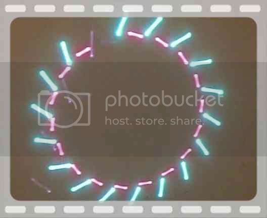
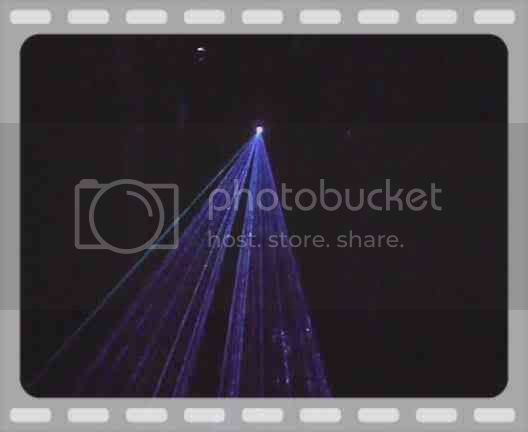
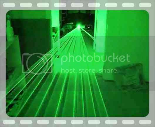
Here’s some video of the completed DAC in action:
Anyone with questions can feel free to PM me.