OK, well, if you find some on ebay, let me know, I can buy them, or see what I have.
1 Like
Thanks Chris, but I may not need to. I’m trying to drive the cost of this project down as much as possible for the both of us. Want to limit how much money is put into this just in case of failure .
This will essentially do the same thing when combined with the horizontal rotation stack as well.
1 Like
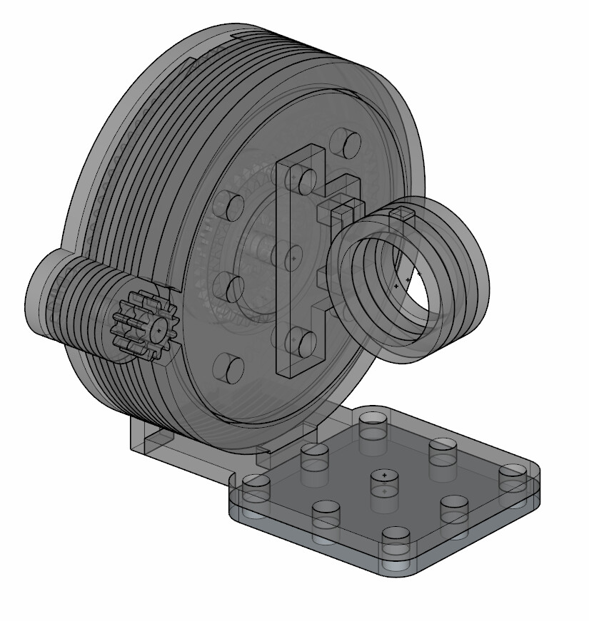
Made a prototype. The real thing would not look that tall. Its constructed purely out of 3mm acrylic. The actual mount is out of a mix of 1/2mm acrylic.
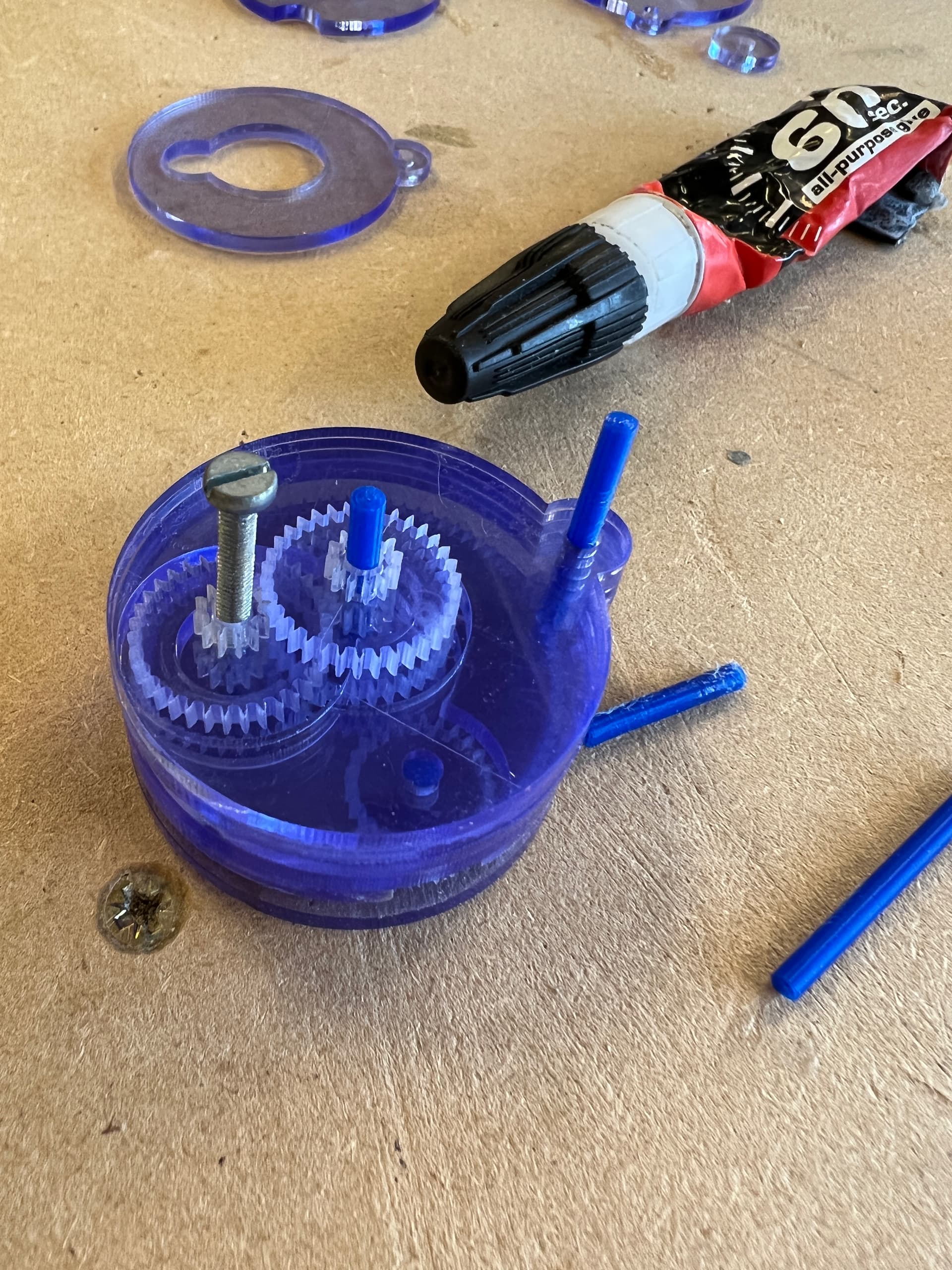
I need to make it mechanically simpler however. I’ll be removing the small drive gear as it doesn’t provide enough torque to turn the gearbox so is pointless. I won’t be including a low res gear, either, so I will have less parts and can focus more on getting the gearbox to work. The gears turn successfully in stages. But full assembly failed due to torque and alignment issues. This was caused by having separation between certain parts. Removing the complexity will allow for better alignment of the gears.
1 Like
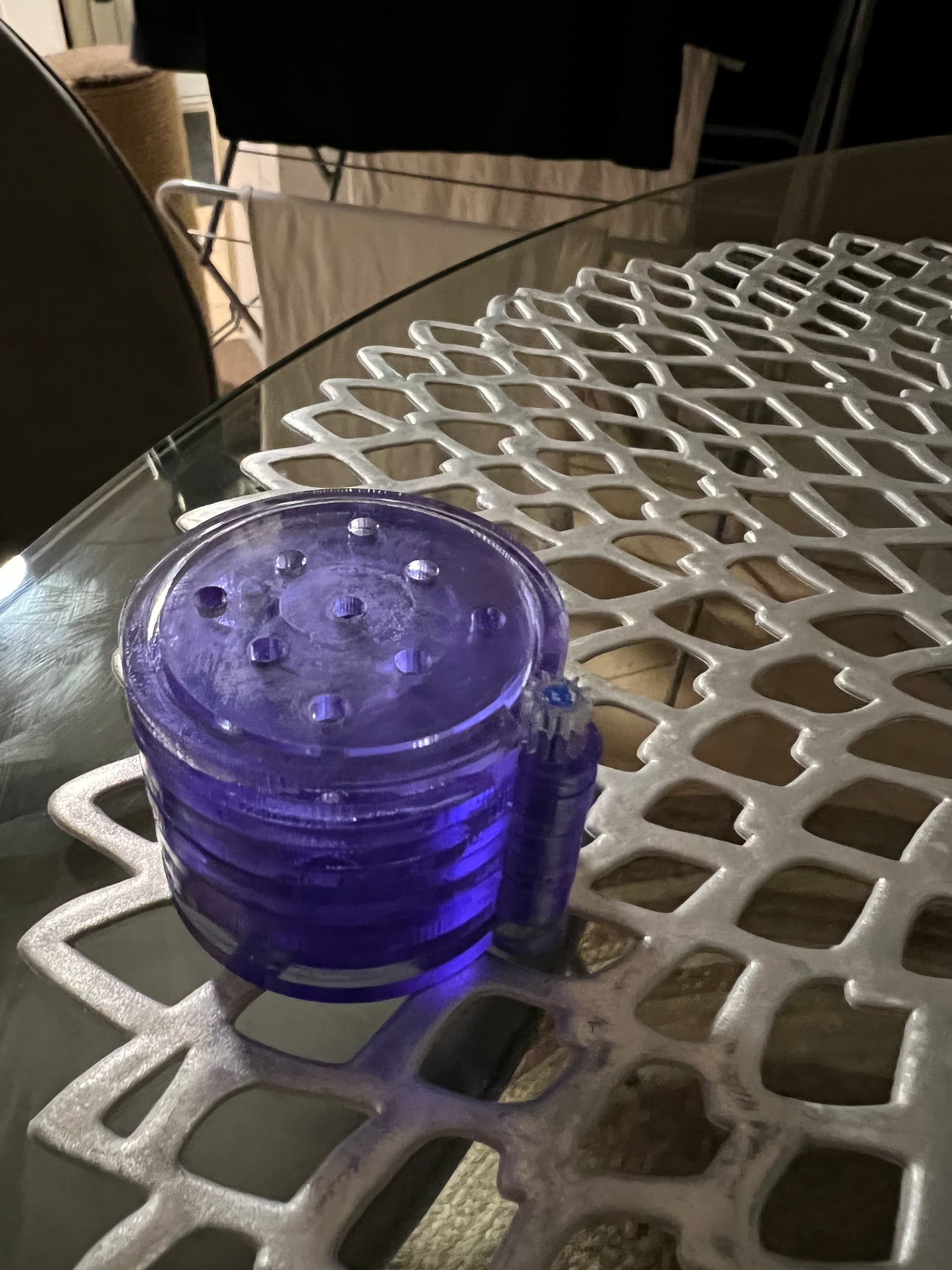
Redesigned the rotation stage hopefully for the final time. 3rd time lucky 
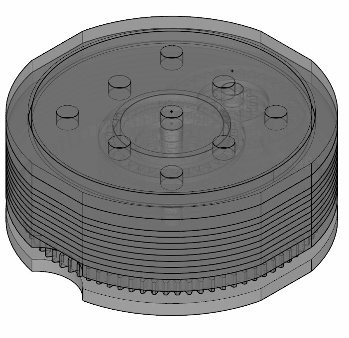
Internal gears:
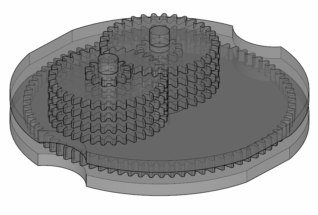
This stage is capable of 0.09° (5.2 arcmins) as well.
1 Like
My best estimates for cost for each mount have been calculated accounting for shipping as well.
This includes the acrylic rods, acrylic sheets, nuts and bolts.
Rotation Stage (H): £1.63
Rotation Stage (V) with mirror mount: £1.74
Lift Stage: £1.79
Translation Stage: £0.71
The cost of all the optomechanical parts in the laser system will come to £36.52. This includes: 5x Rotation Stages (H), 6x Rotation Stages (V) with mirror mounts, 6x Lift Stages, and 10x Translation Stages. The cost of buying all these equivalent components would come to a staggering £4094.16. That is extortionate.
@terho Not finished designing yet hence some parts still floating. 
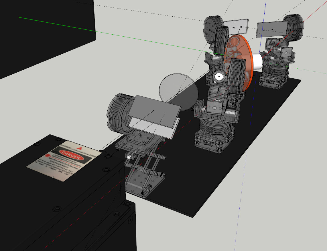
But I am starting to wonder whether this thing is overengineered. 
2 Likes
So this is the importance of planning things out as thoroughly as possible.
Here is a log of changes:
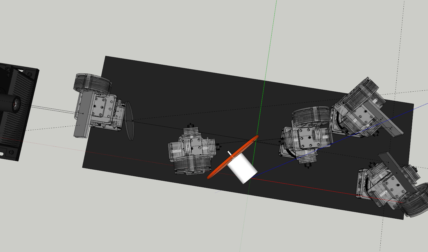
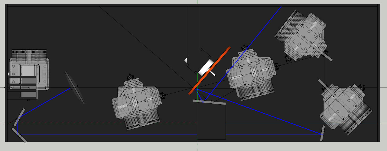
I’ve changed the optical layout slightly to allow for changing of the laser disc. With the mounts it was a tight fit and would of required realignment every time one is replaced. The laser disc is now rotated and so the laser path is directed through the rear instead of the front.
I have also added mirrors to reflect the transmitted pump beam back onto the PMMA. It will essentially act like another pass if I can figure out a way of deforming the acrylic mirror precisely to become convex. This will improve the overall efficiency. If I can work out a way of directing the reflected pump back onto the PMMA without interfering with the laser cavity then I’ll will update it.
The fold mirrors are now longer to account for optical clipping on the mounts themselves.
I have removed the need for one rotation mount by featuring a fixed mirror to fold the pump beam into the cavity.
The lens has been rotated now to 30° to account to eliminate all chances of back reflection. I have checked the result of this on the cavity and it only alters the focal length on the pump beam a minor amount. I am experimenting with reflecting the waste reflection and reutilising it within the PMMA as well.
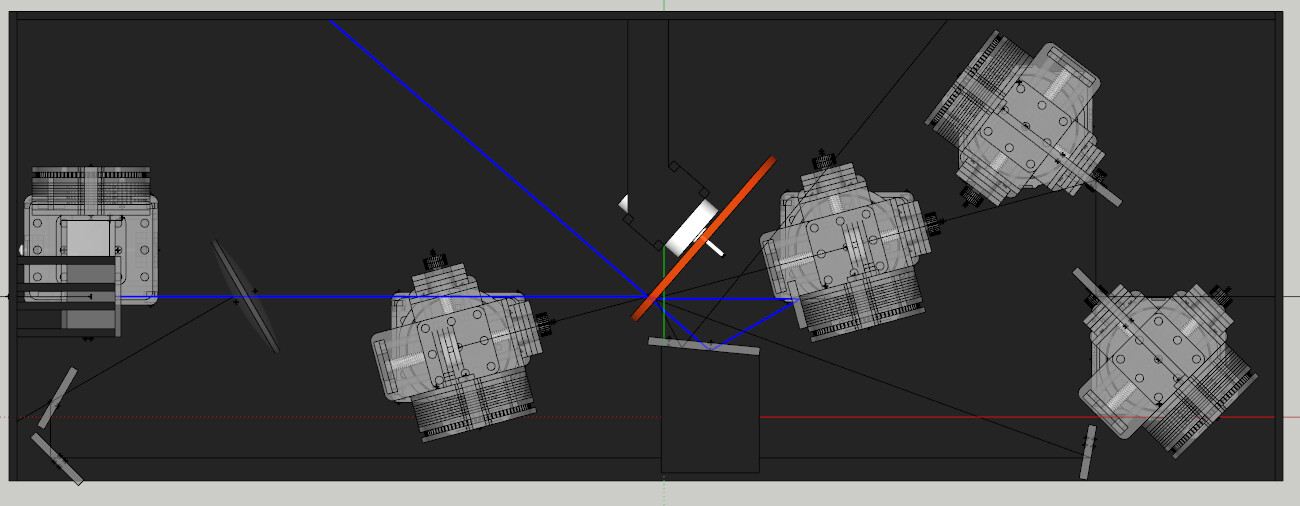
Here is some ray tracing so I can recycle the waste beams.
Lens back reflection pass:
Transmission pass:
1 Like
What’s the design program you are using on this?
I’m a bit envious of your skills!
I’m using Sketchup and 2D design V2 for all this.
It’s years of experience on these softwares. I’ve just learnt how to draw accurate ray tracing on 2D design. It’s all manual however. Every ray I have to draw based on reflection/refraction calculations.
Phew… I thought you’re using Zemax 3D or similar ![]()
![]()
1 Like
No😂. I have no fancy software. Everything is manual work. I use a online JavaScript program for quick optical tests. But then the accurate stuff is manually calculated and drawn.
Hmm… Should I ask trial for my EDU? 

Wow. In our dreams lol
Looking a the laser mirrors like this just looks like a random mess.
I now have simulate the rays to find out how the divergence of the pump beam interacts with those mirrors. I might have to put additional lenses in place.
1 Like
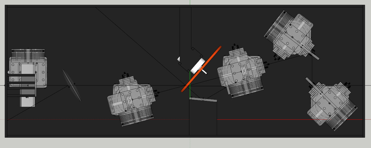
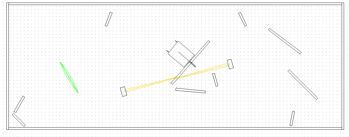
Ray tracing as of now.

Need to continue the pump beam path around the whole system. Due to the divergence I may need to use a lens to refocus the rays again. But regardless, that spot on the PMMA between the laser cavity will get a pummelling.
The green laser is calibrated to that of real beam specs of the 4.25W DPSS I plan to pump with. That simulation is as close to reality I’ll be able to realistically achieve without specialist software.
Edit: Need to recalibrate the refractive index both for BK7 and PMMA based on 532nm. Shouldn’t drastically change anything though. Then it will be the ultra realistic. 
1 Like