Nik's Pr:YLF 640, 607 and 523 nm Laser Project

Above: YouTube Video. Below, article from Niklas Hammerstone’s web page. Nik, if you find this forum, please join with us.


The following cut and paste from: Diode pumped Pr:Ylf-Laser emitting at 640, 607 and 523nm. — Sci-Projects: Science and engineering at home!

Diode pumped Pr:Ylf-Laser emitting at 640, 607 and 523nm.

Only a few known laser materials are able to emit visible laserlight from visible pump light. One of those materials is the praseodymium ion (Pr3+), which is often doped into Yttrium-Lithium-Fluoride (Ylf) crystals. But Pr:Ylf is not only interesting due to this property. In the following article, I’ll walk you through what makes Pr:Ylf even more special and how one can use this material to make diode pumped solid state (DPSS) lasers emitting at different visible wavelengths with the exact same crystal.

Properties of Pr:Ylf

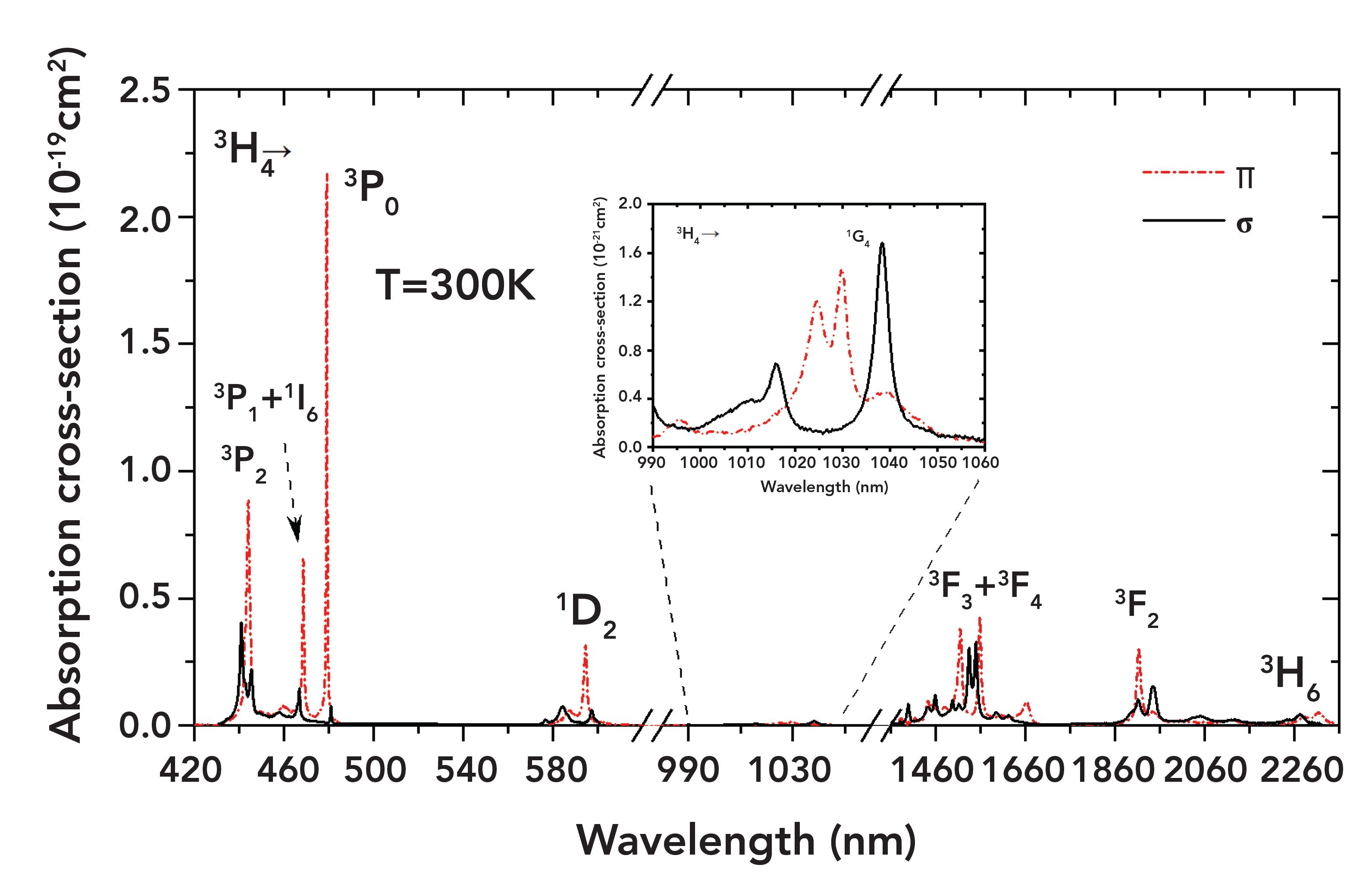
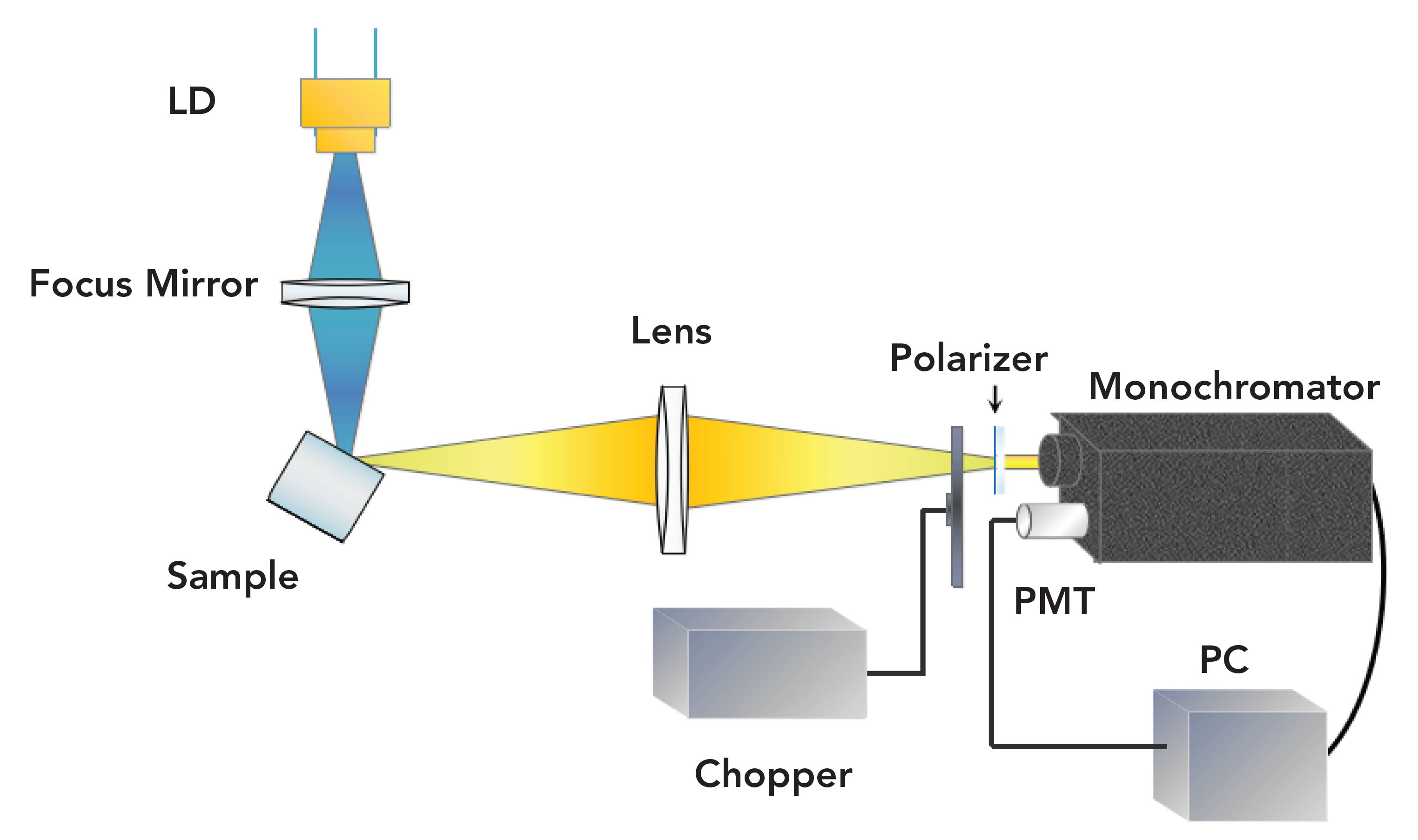
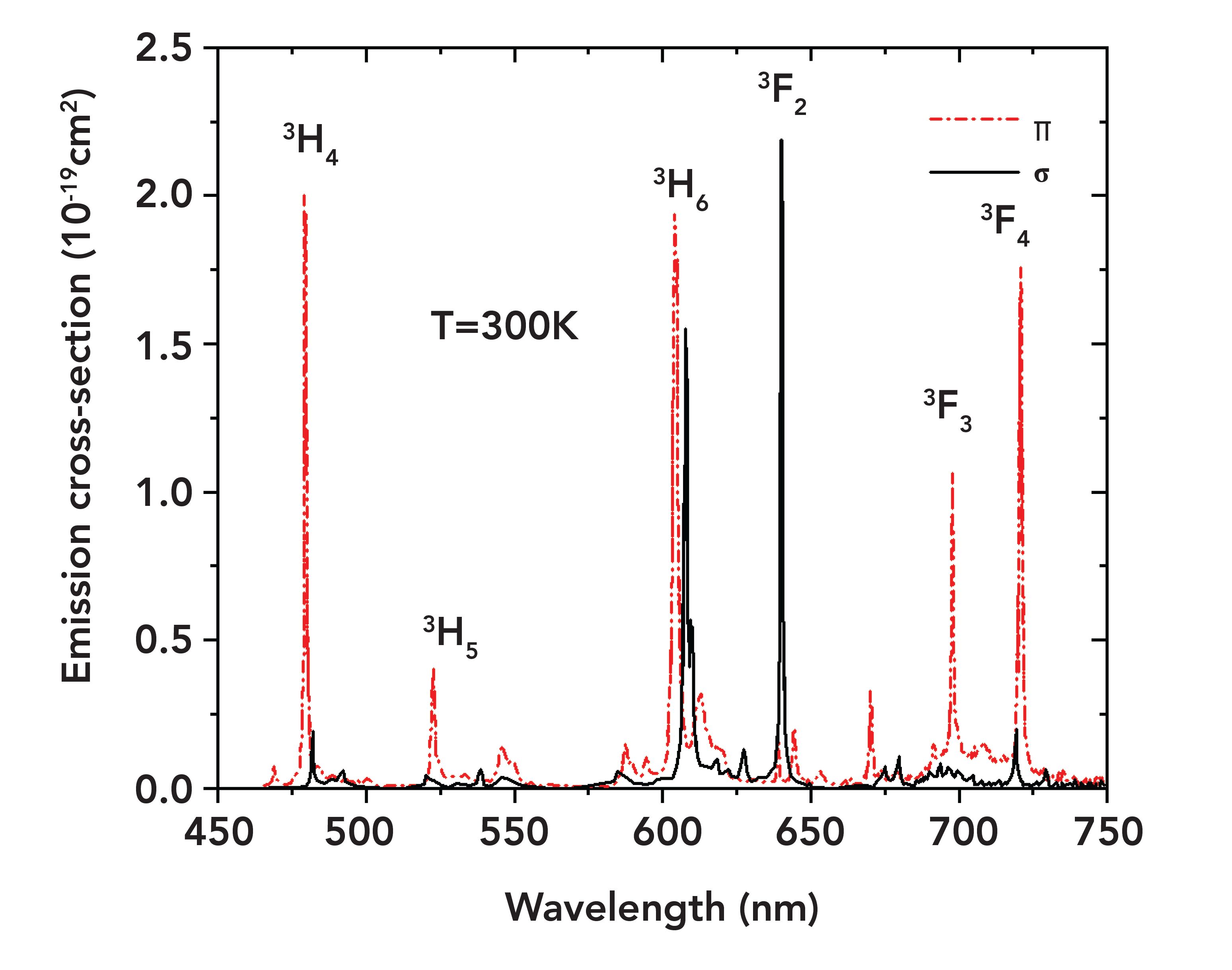
In order to understand the optical properties important for laser design, we need to look at its absorption and emission spectrum.

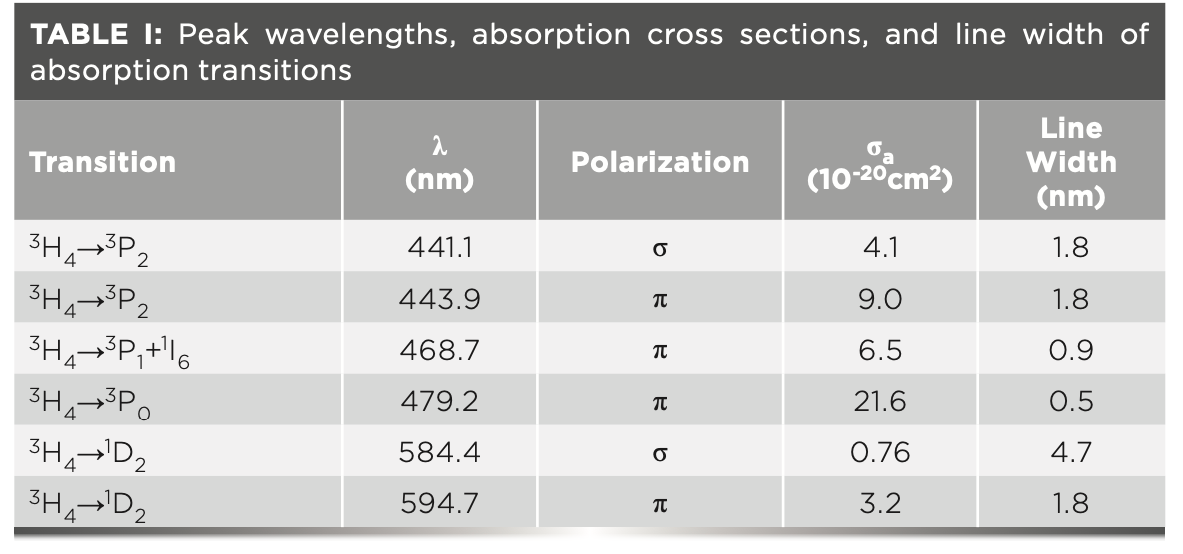
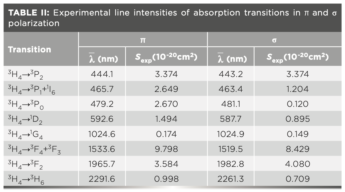
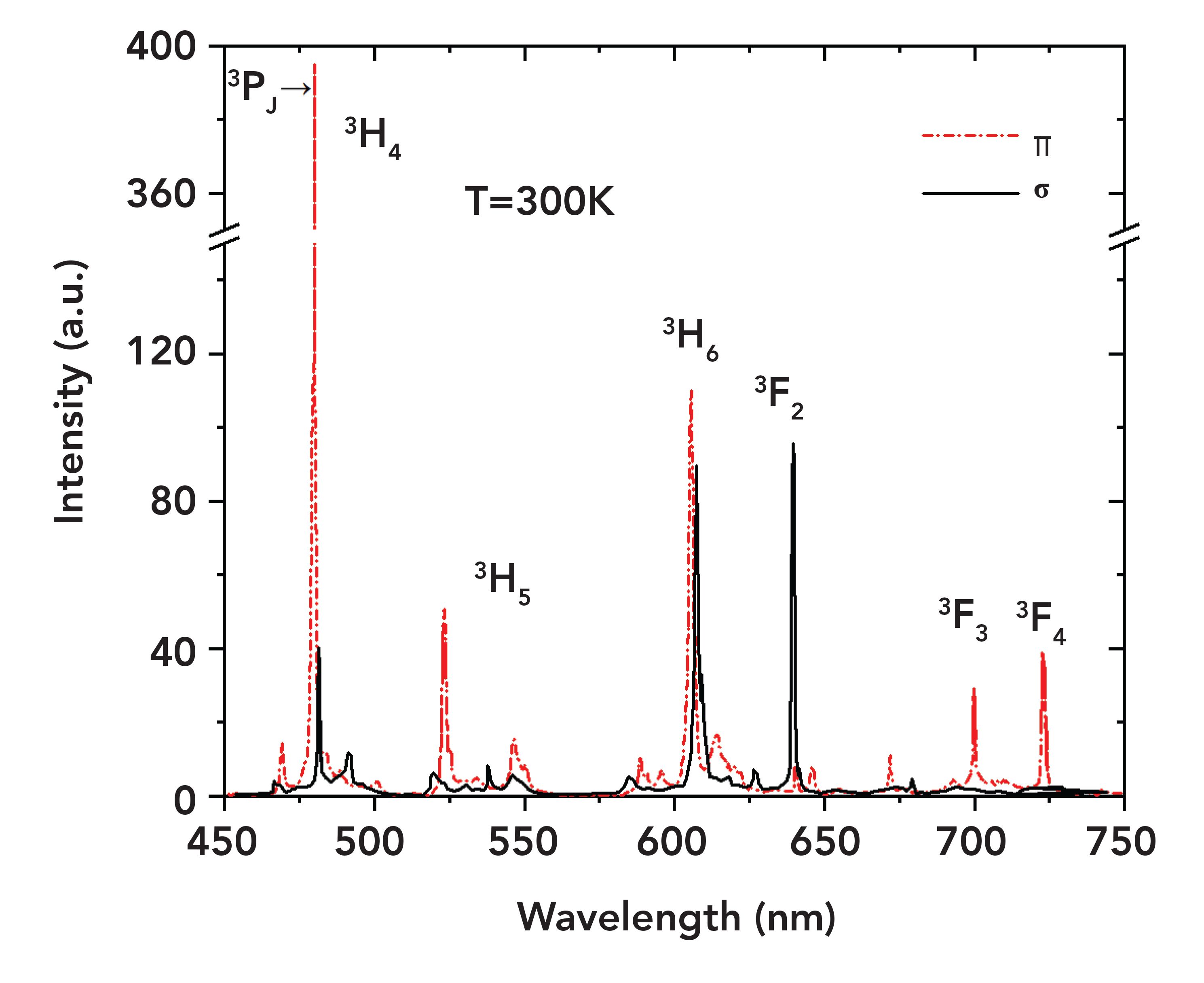
Absorption and emission spectrum of a-cut Pr:Ylf with doping concentration of 1 at.% [[OPTOGAMA]]

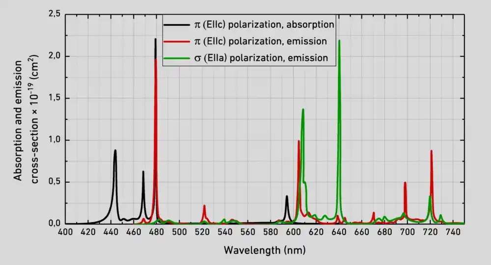
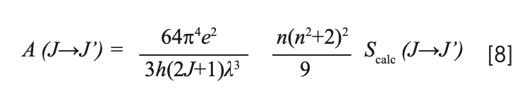
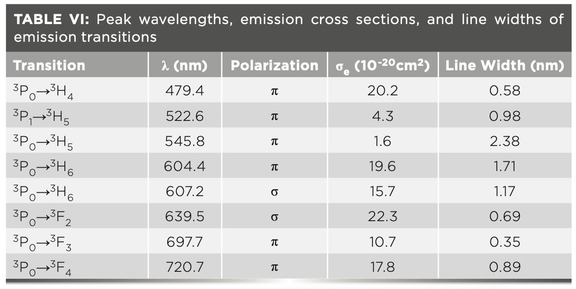
First of all, you can see that there is a very strong absorption peak at 444nm. Therefore, a pump source of this wavelength would be relatively efficient. This is great, because there exist 445nm laser diodes with several watts of optical powers available at very reasonable prices (see chapter Laser design). It is also apparent that Pr:Ylf has a lot of strong emission peaks, depending on polarization. So, not only can it be pumped with visible light and emit visible laserlight, but it can also support a multitude of lasing wavelengths! For example, high emission emission cross-sections at 607nm and 640nm promise high output powers at these wavelengths. There are also notable peaks at 480nm, 523nm, 692nm and 720nm, of which only the peak at 523nm will be of interest in this article. It is obvious that the peak at 523nm has a much smaller amplitude compared to the two peaks mentioned above, so we would expect less output power at this wavelength.

Lastly, we can see that the properties are polarization dependent, so we will have to keep the relative alignment (“roll”) of the pump and the crystal in mind.

Laser design

Going from these properties, we now need to design the pumping source and the laser resonator. Lets start with the resonator, since the pumping source depends on how the resonator is set up.

The resonator

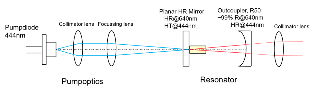
The resonator is the core of any laser. It allows the photons to pass through the excited laser material multiple times, getting amplified each time. There are multiple ways to combine plane, concave and even convex mirrors with each other to make different resonator types with different properties. In this case I chose a hemispheric resonator, which means it consists of one plane (HR, high reflectivity) and one concave (OC, output coupler) mirror. This resonator type is optically quite stable and allows for slight misalignments in the HR mirror without losing resonance. In this article about a DPSS ruby laser I already described this in detail. In order to get sufficient feedback in the resonator, the reflectivities of the mirrors need to be quite high. For the output coupler for the 640nm line (I’ll talk about the other wavelengths further down the article), a reflectivity of about 99% @640nm is used. Transmission values of about 1% for the OC are quite common in the world of continuous wave DPSS lasers. The HR needs to be as reflective for the laser wavelength as possible. Since the crystal I used (2x2x6mm, 0.8% doping), is only polished at the longitudinal faces, the only reasonable pumping method is end-pumping: The pumplight will be focussed into the crystal through the plane HR mirror and excite the laser medium this way. Therefore, the HR mirror must also be quite transparent to the pumping wavelength, in this case 444nm. Both of the mirrors must be mounted in adjustable kinematic mirror mounts. The alignment of the crystal is not as critical since its faces are very parallel to each other, so it will be fixed to a simple metal mount.

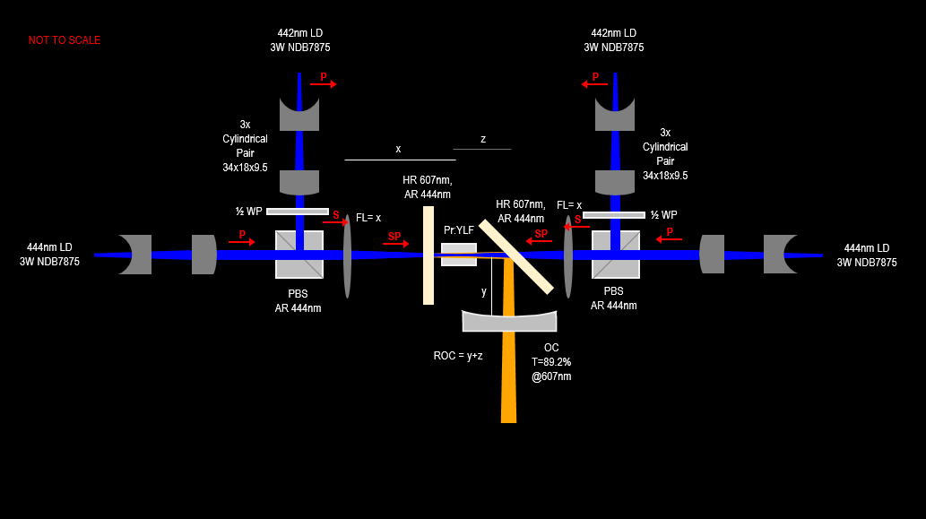
The pumping sourcing

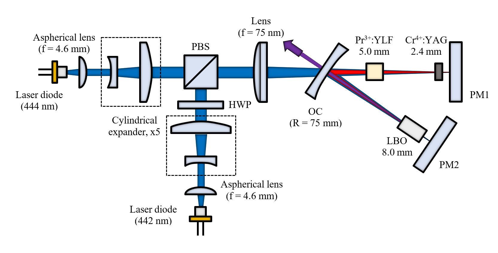
Since 445nm laser diodes with high output power exist widely available, choosing one of them is a rather obvious decision. But: since the gain bandwidth of the medium is only a very few nanometers, you’d be lucky if your diode emitted exactly the 444nm that Pr:Ylf needs. Remember that those 445nm diodes usually come with pretty large manufacturing tolerances regarding the output wavelength and also suffer from wavelength shift at different temperatures and currents. To eliminate this uncertainty, I bought a wavelength-selected diode (Type NDB7875) that is guaranteed to emit at 444nm under the specified operating temperature and current. The output beam of the diode is highly divergent and therefore must be collimated before it is focussed into the crystal. I used a combination of an aspheric collimating lens (f=4.6mm) and a biconvex focussing lens (f=50mm). The setup is visualized in the picture below. Note that I also used an edge filter behind the final collimating lens in order to get rid of any transmitted pump light. The resonator length is about 50mm.

The pumping module has quite a lot engineering constraints attached: It must

  • securely house the optical components,
  • be able to (in this case) watercool the diode to prevent overheating,
  • have an attachment point for a temperature sensor,
  • be able to be mount into an adjustable kinematic holder,
  • be free to rotate, in order to adjust the relativ “roll” of the pump polarisation and the crystal.

The final design which solved those constraints can be seen in the pictures below.

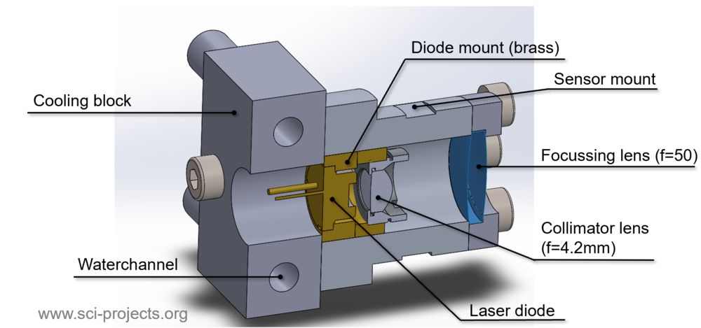
Sectional view of the CAD Model

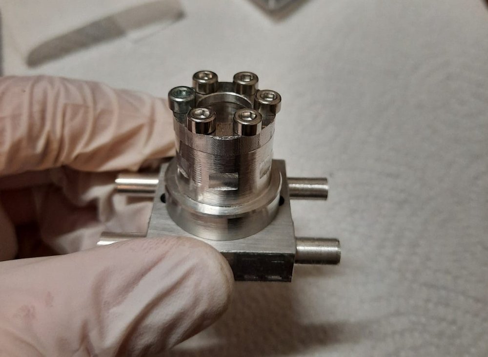
Picture of the finished module made from aluminium and brass parts

This design allow watercooling through waterchannels in the cooling block. This is attached to the main housing pieces in which the laser diode is seated. This very compact design also has flat milled sections which allow the attachment of a TO-92 style temperature sensor.

Design implementation

Let us now look at how I put the aforementioned puzzle pieces together. The optical train was realised by mounting the adjustable kinematic holders onto shaft holder trusses (see picture below).


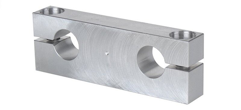
Shaft holder truss by [Dold Mechatronik]

Due to the precise machining of these components, they can be mounted onto two precision rods with little to no play. With a little bit of light oil they move freely along one common axis but can also be clamped very tightly once the alignment is correct.

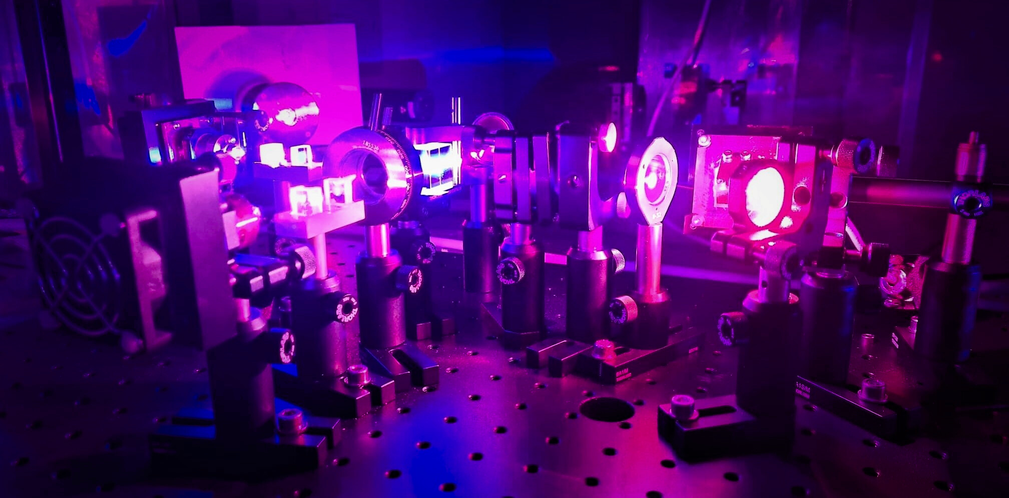
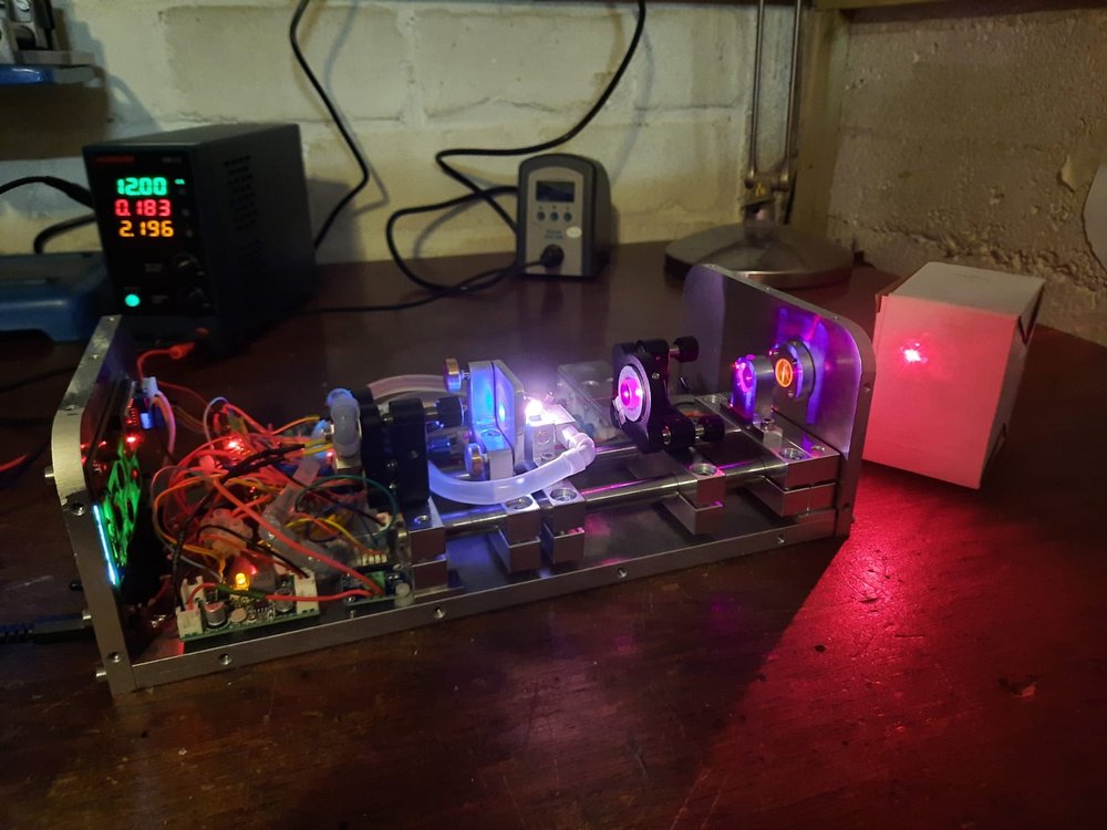
Since one of the main goals for this project was to make a easy to use laser module which would remain functional even after years of being stored in a dusty basement, I mounted the components onto a sturdy aluminium base plate and bent an alumium sheet as a dust cover. This, by the way, is also the reason why air cooling was not an option for me: If dust were to settle on the optical interfaces it could get baked onto them by the laserbeam and destroy them. The module (without the dust cover) can be seen in the picture below. The combination of the base plate, the hardened precision rods and the trusses makes the setup very sturdy, I can easily carry the module without worrying about the alignment. The trusses at the end are, of course, bolted to the base plate.

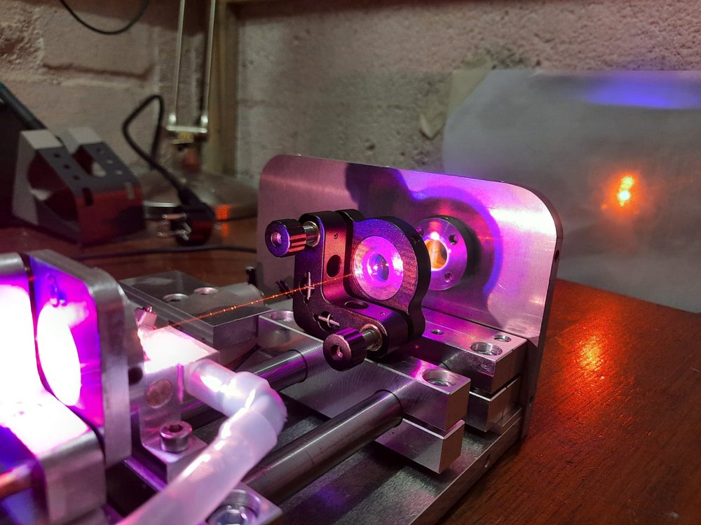
As you can see, I used professional mirror mounts (Edmund Optics) for holding the pump module and the output coupler since their alignment is fairly critical. For holding the HR mirror I used a homemade mirror mount since its alignment is not as critical. The holder for the Pr:Ylf crystal is a machined aluminium block. Since the crystal only needs to be translated along the optical axis, it is fixed onto the holder using a very tiny amount of thermal adhesive.

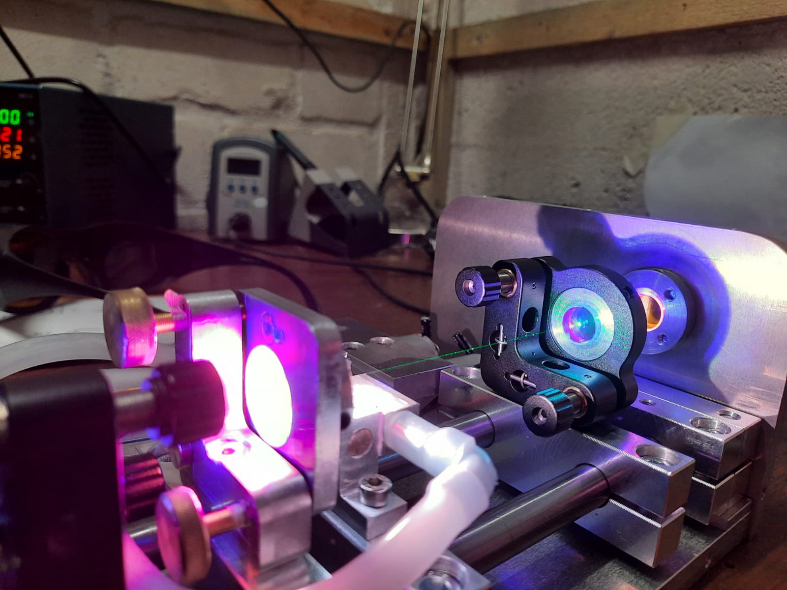
You can also see, besides the beautiful white glow of the crystal, that the module is packed with electronics, which I’ll briefly describe in the next section.

Electronics

In order to maximize the usability of the module, I used an Arduino Nano which measures the diode current, diode temperature, crystal temperature and calculates pump power from the measured current. This information, along with the system status is displayed on a LCD Screen.

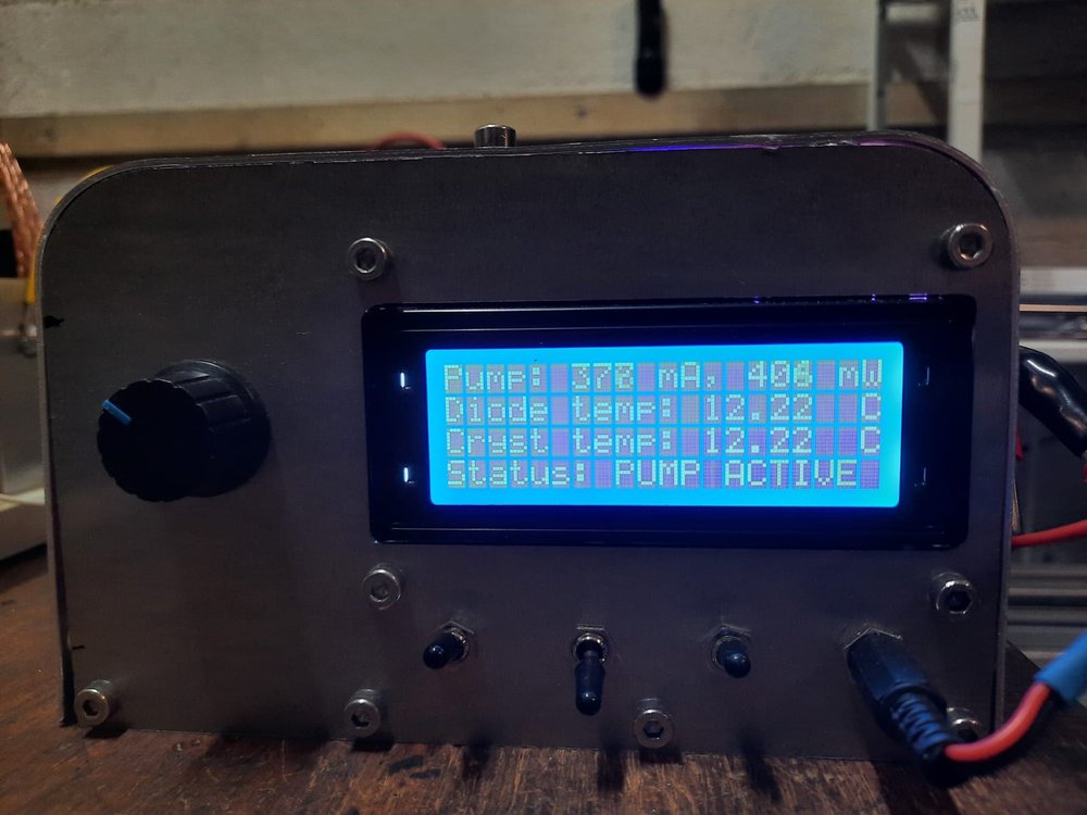
The diode driver is controlled by a potentiometer on the front panel. In the picture above you can also see three switches: The right one switches the power to the module, the left one arms the diode driver and the middle one enables active cooling. Once this is activated, two onboard waterpumps circulate water through the diode module and the holder of the crystal. If one of the temperatures reaches a set limit, peltier elements activate and cool down the water going through the overheating element. In practice though, this rarely happens. Also, active cooling of the crystal did not prove to be necessary at the pump powers (<1.2W) I am using. For a detailled electrical schematic and codes please refer to the project’s GitHub repository.

Mirror alignment

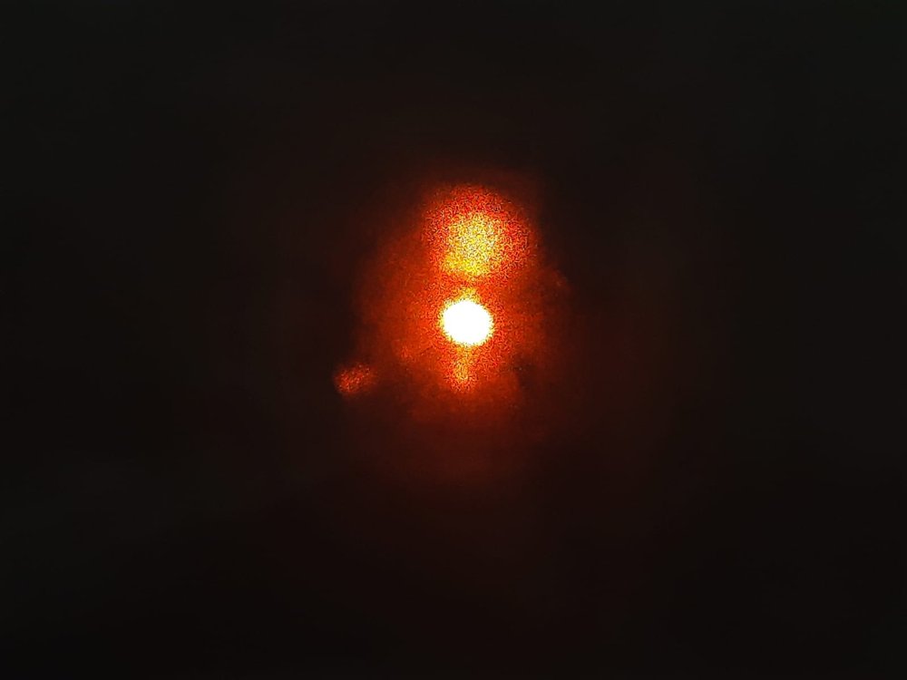
Before we look at the results, lets quickly discuss mirror alignment. This can be quite tricky but if you use the right alignment strategy, it can be done quite effectively. For the ruby laser, looking into the crystal and visually aligning the pump and mode volume worked fine, but since the Pr:Ylf fluoresces much more, it is too bright to see the volumes (even with laser goggles on) once the pump diode thresholds. A much better strategy is to align the cavity by aligning the OC so that the two appearing spots on the output coupler are exactly on top of each other. The first one of the spots is the direct spot of the pumplight. The second spot appears for the following reason (at least I think this is the reason): The pumplight enters the crystal, excites it and creates a weak beam of 640nm photons in the same direction as the pumplight. The beams now hit the OC (this is the first spot) and get reflected into the crystal, where even more coherent photons are created. Since the HR is transmissive for the pumplight, only the 640nm photons get reflected of the HR, pass the crystal once again and hit the OC, creating the second spot. Once the spots are aligned, the beam can resonate back and forth without straying from its path and lasing occurs. This strategy is explained very well in this document by Dr. Walter Luhs. In the picture below, I tried to visualize the strategy as well as I could. Note that the 444nm spot also contains a spot of the laser wavelength, but outshines it by orders of magnitude which is why you can only see the pumplight unless you have got very good goggles. The second spot is very dim, I only was able to see it by switching off the roomlights and very gently blowing on the mirror so that the light condensation (my workshop is quite cold) increased scattering.

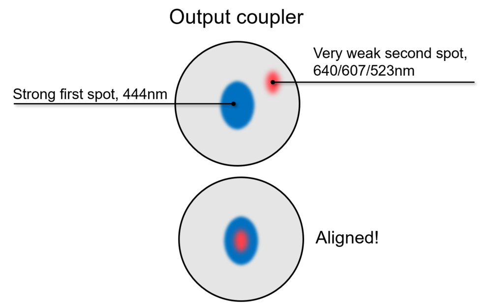
Note that for the 607nm mirror, the spots were also visible on the wall behind the mirror which made alignment a lot easier.

Results

The first set of mirrors I used was the mirror set originally intended for the DPSS ruby laser. This allowed the strong 640nm line to get amplified. One short note on this: In this setup, usually only one line gets amplified. As soon as the material is pumped to threshold, the different lines “compete” and the strongest line wins and “takes it all”. Therefore, mirrors for different wavelengths must suppress the stronger lines (e.g. by having low reflectivity for them) in order to get the desired effect. However, this is not necessary if you just want the strongest line to lase, which was the case for the first experiments I did. After aligning the mirrors, the laser produced a very beautiful red output which was quite strong, on the order of 100mW or more, depending on pump power. It also produced some of the most spectacular transverse mode patterns (TEM modes) I have ever seen.

640nm laser action. The intensity inside the resonator is so high that the beam is visible without any smoke in the room. Here, the beam has more or less in a round shape, it operates in a TEM00 mode.

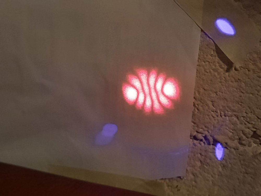
When the mirrors are almost (but not quite) perfectly aligned, the beam is not circular but assumes a more interesting shape, a higher order TEM mode. This is a very clear example of one of those shapes.

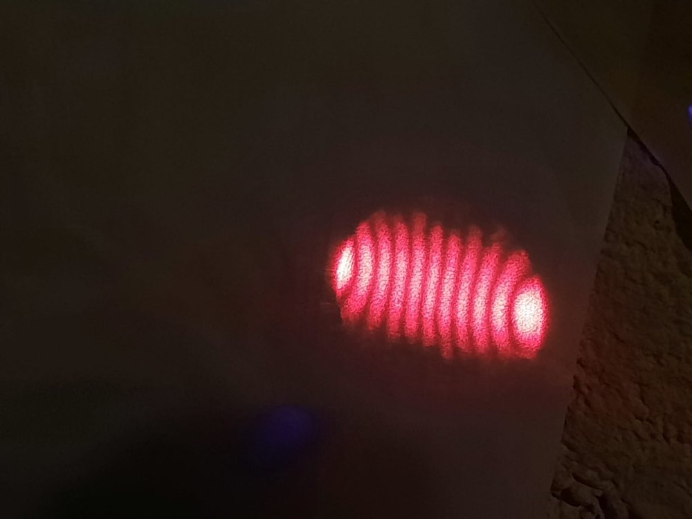
This is another example for a very interesting TEM mode. The mode is not fully visible due to the aperture of the output window.

Now, in principle, getting the setup to lase at different wavelengths is just a matter of using a different mirror set. And this worked very well for getting 607nm output, which is orange. I used a concave mirror (R=-100mm) explicitly designed to suppress the 640nm line and the same HR to get the results you can see below. Since the 607nm line is almost as strong as the 640nm one, the output power is very similar.

Apart from some inconsistencies in the beam probably due to imperfect cleaning of the optical elements, the spot is very round. Similarly to the setup above, the intracavity beam is clearly visible.

Here’s a close look at the beam.

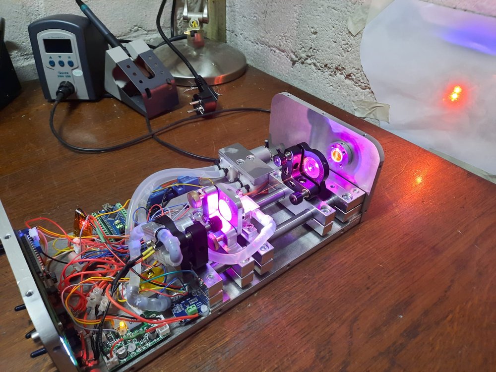
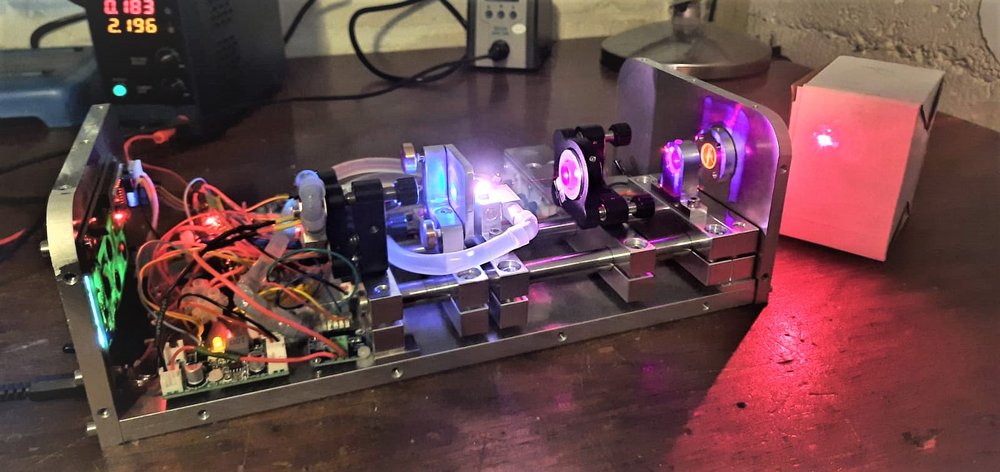
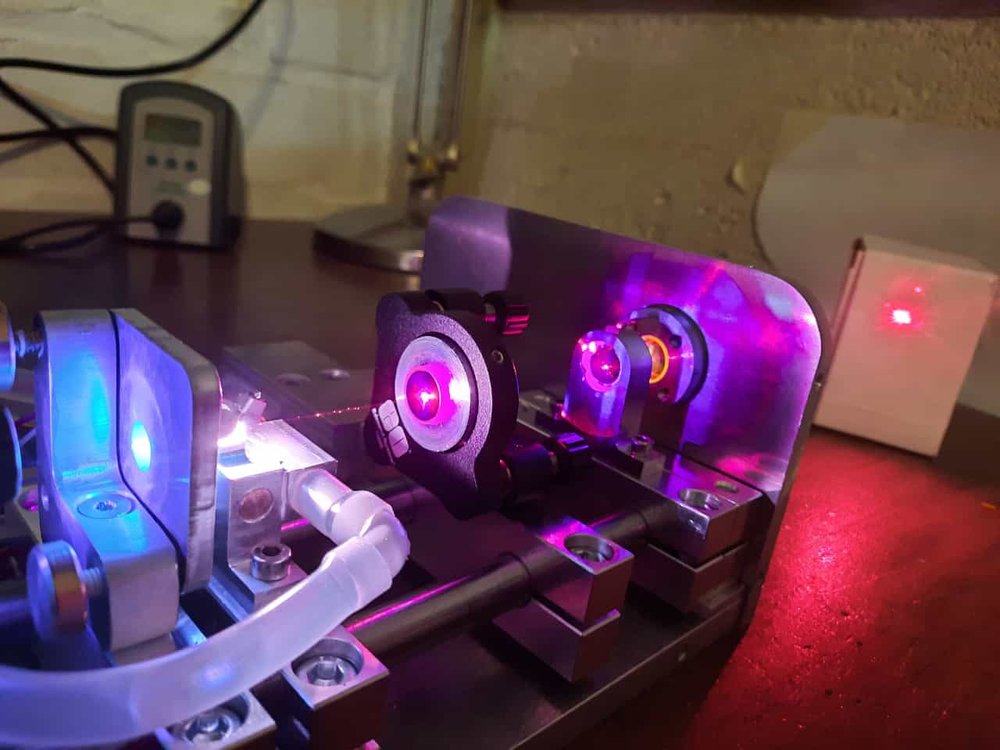
Here’s another picture of the setup as a whole. Here you can also see the waterpumps, the arduino and a whole lot of wires.

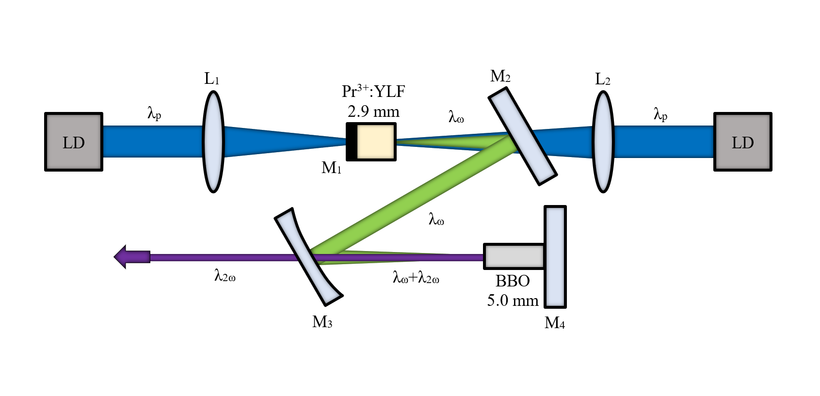
The wavelength I was really excited about is 523nm. Since the mirror I had for 523nm had virtually no transmission at 523nm, the setup for this wavelength looks a bit different:

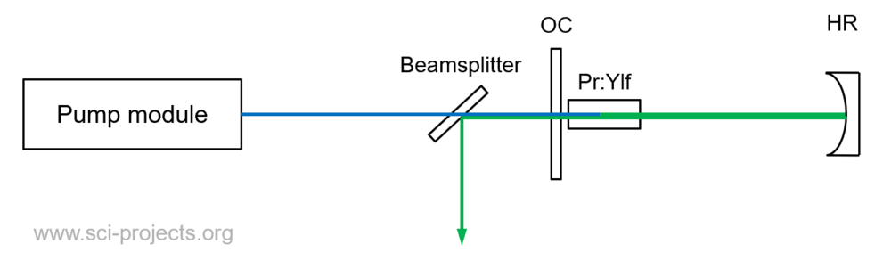
This setup utilizes the fact that the plane HR mirror I had originally bought for 523nm has about 0.5% transmission @523nm and can therefore be used has an output coupler. The concave mirror acts as the HR. Since the laser output now emits into the direction of the pump module, it is selectively reflected using a beamsplitter. Using an edge filter to filter out the few percent of the pumplight yields quite a strong green beam.

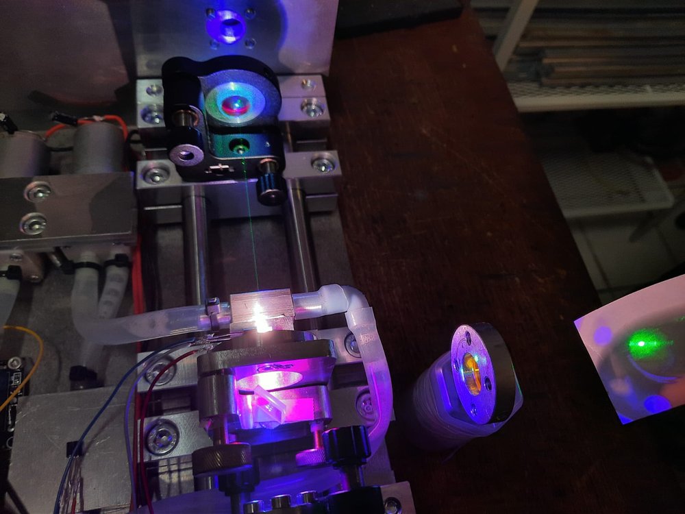
Again, the intensity inside the resonator is very high. The additional element in the optical train (referring to the beamsplitter) does make the beam profile a bit inhomogenous, but as you can see, the core “dot” of the output is round.

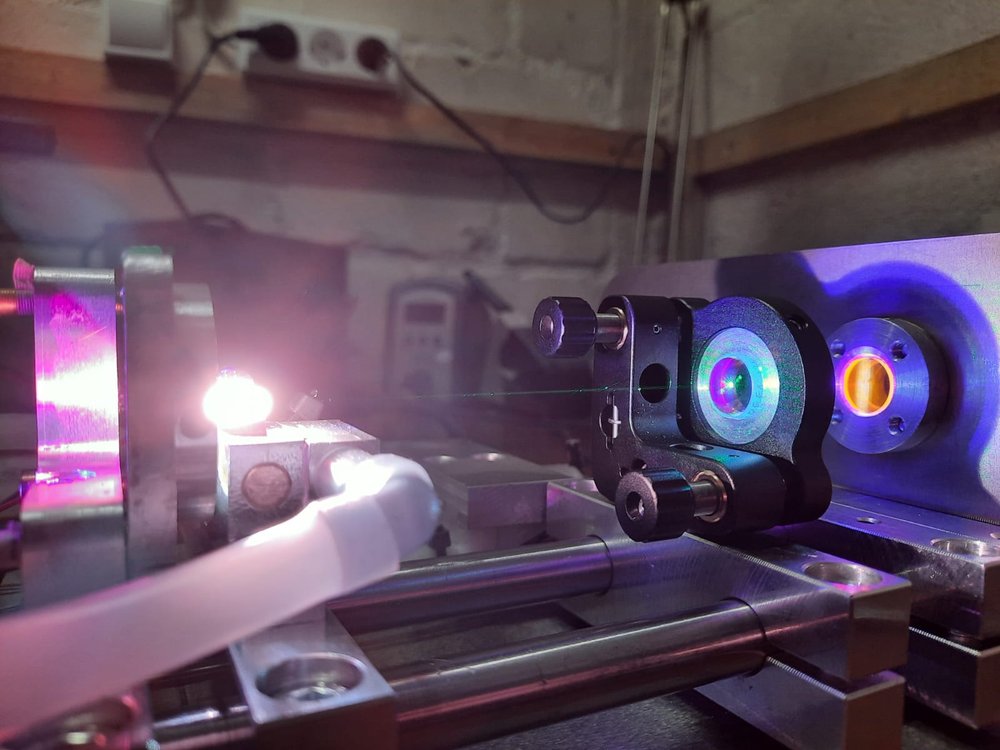
A beautiful shot of the green intracavity beam emitted from the fiercely fluorescing crystal.

As expected, getting the 523nm line to lase is relatively difficult in comparison to the previous two lines. The alignment is a lot more “fiddly” and the threshold current is pretty high (around 700-800mA). However, looking at the beautiful green output, this has all been worth it.

I can not (yet) provide reliable information on the output power of the module but I will be able to do that very soon. At least for 640nm and 607nm, I am confident that I can exceed 100mW of output power.

So, as you can see, it is possible to utilize this wonderful material, Pr:Ylf, to achieve multiple distinct visible output wavelengths using a relatively simple pumping method. I hope you enjoyed reading this article as much as did making this laser!

Thank you so much for reading,

~Nik

From: Diode pumped Pr:Ylf-Laser emitting at 640, 607 and 523nm. — Sci-Projects: Science and engineering at home!

1 Like

Update from Nik: GitHub - NiklasHammerstone/PrYlf-Laser: This repository contains the documentation for a homemade Pr:Ylf-Laser. - Go to this link for more info, more there than I can post here.

PrYlf-Laser

Update 19.01.2021 Orange Output!

Using another mirror, the lasers now also lases at the orange line (604nm). The output power is similar to the 630nm line, but not quite as high. 604nm Laseraction

Update 18.01.2021 Intracavity green!

I was able to use a specialized mirror to successfully amplify the green (523nm) line of the Pr:Ylf crystal. Now I need to find a way to couple it out… Intracavity green

Update 28.11.2021 First red light!

The laser module now emits red light at around 630nm. The divergence seems to be around 1.7mrad.

Laser action

The module can produce quite high order TEM-modes, but a TEM00-Mode can of course be obtained.

1 Like

More info from 4lasers.com

1.1. High power CW visible Pr:YLF laser

Diode-pumped CW visible Pr:YLF laser setup is based on H. Tanaka et al. article [1]. 4Lasers provide all the necessary optical components according to the previously mentioned article in order to assemble the Pr:YLF laser. The principal scheme of the laser setup is presented in Fig. 1.

Figure 1. Laser setup of high power CW Pr:YLF laser

As a pump source four single-emitter laser diodes, each emitting a maximum output power of 5 W in the central wavelength of 442 nm and 444 nm are used. It should be noted here that for a good spectral overlap of the LD emission spectrum and the crystal absorption spectrum the stabilization of LD temperature by Peltier modules should be applied.

Since the LD emitter has a rectangular stripe shape, each beam coming from the LD is extended along its slow axis by a factor of five using a cylindrical lens pair (f = −20 mm and 100 mm) in order to improve the mode-matching efficiency with the astigmatism-free cavity mode. Expanded beams are then combined at the polarizing beam splitters and focused by spherical lenses (f = 120 mm and 150 mm) into the laser crystal.

The laser resonator consists of three mirrors: two plane dichroic mirrors (DM) and an output coupler (OC) with a radius of curvature of 100 mm. The DMs must have a high reflectivity (HR > 99.5%) for 520 – 650 nm and a high transmission (HT > 98%) for 430 – 450 nm. The OC with a transmission of 5.2% is used for the laser operating at the wavelength of 640 nm. For the 607 nm laser operation an OC with a transmission of 10.8% at 607 nm and T > 90% at 640 nm is used. The cavity length should be optimized in order to obtain the maximum output power (lcav ~ 72 mm). As an active element (AE) the 5 mm diameter and 12 mm length AR coated (for both pump and laser wavelengths) rod cut perpendicular to a axis from 0.3 at.% Pr3+:YLF crystal is used. Water cooling of the gain medium is recommended.

Note that every optical element can be customized according to customers request.

Expected lasing parameters

4Lasers does not take any responsibility if the achieved lasing output parameters are not as described in the [1] article. Maximum output power at a maximum absorbed pump power of 15 W was 6.7 W and 3.7 W at 640 nm and 607 nm, respectively. The slope efficiency with respect to the absorbed pump power was calculated to be 45.5% and 30.0% at 640 nm and 607 nm, respectively.

1.2. CW UV Pr:YLF laser

Laser setup description

Diode-pumped CW UV Pr:YLF laser setup is based on T. Gun et al. article [2]. 4Lasers provide all the necessary optical components according to the previously mentioned article in order to assemble the Pr:YLF laser. The principal scheme of the laser setup is presented in Fig. 2.

Figure 2. Laser setup of CW UV Pr:YLF laser

As a pump source two InGaN laser diodes with a maximum output power of about 1 W each are used. A folded Z-type cavity enables pumping from two sides and provide optimal beam waists both in the gain medium (Pr3+:LiYF4 laser crystal with a dopant concentration of 0.5 at.% with the length of 2.9 mm) and in the nonlinear crystal (BBO crystal with the length of 5 mm). According to the reference article [2], the experimental results were achieved with beam waist radii inside the laser and nonlinear crystals of 50 µm and 53 µm, respectively. Beam collimation and shaping of the LD radiation are performed by using a spherical lens with a focal length of 4.5 mm as well as an anamorphic cylindrical lens pair. The lenses L1,2 of 40 mm focal length should be used in order to focus the pump beams into the laser crystal.

The folded Z-type cavity consists of three plane mirrors (M1, M2, M4) and a curved mirror M3 with a radius of curvature of 50 mm. The two input couplers M1 and M2 are AR coated in the range of 440 ± 40 nm and HR coated (R > 99.8%) in the range of 520 ± 20 nm. The mirror M4 is HR coated for 520 ± 20 nm and 260 ± 10 nm wavelengths. The BBO crystal, (type I phase matching Ѳ = 48.9º, γ = 0º) AR coated at 520 nm is placed in the beam waist located near M4. Most of the generated UV radiation is coupled out through the curved mirror M3 with transmission coefficients T520 nm = 0.02% and T260 nm = 91%. It should be noted that the mirrors M1 - M4 have a total transmission ~ 0.06% at the fundamental wavelength.

Note that every optical element can be customized according to customers’ request.

Expected lasing parameters

4Lasers does not take any responsibility if the achieved lasing output parameters are not as described in the [2] article. Maximum output power of 481 mW at 261.3 nm can be achieved at the absorbed pump power of nearly 1.3 W. An optical-to-optical efficiency of 26.1% with respect to the total pump power can be expected.

1.3. Q-switch UV Pr:YLF laser

Laser setup description

Diode-pumped Q-switch UV Pr:YLF laser setup is based on H. Tanaka et al. article [3]. 4Lasers provide all the necessary optical components according to the previously mentioned article in order to assemble the Pr:YLF laser. The experimental setup is presented in Fig. 3.

Figure 3. Laser setup of Q-switch UV Pr:YLF laser

The laser is pumped by polarization-combined InGaN blue diode lasers whose output power is 3.5 W. The diode pumps are collimated by an aspherical lens (f = 4.6 mm) and expanded five times by the cylindrical lens pair (f = −20 and 100 mm) along the slow axis to shape a symmetric focal spot. The pump beams are combined at the polarization beam splitter (PBS) and focused into the gain medium (Pr3+:YLF crystal 5.0 mm long, cut perpendicular to the a-axis with a doping concentration of 0.5 at.%) through a spherical lens (f = 75 mm). All lenses are AR coated in the range of 440 ± 40 nm. It should be noted that the expected lasing parameters can be obtained with a spot radius ∼ 32 × 48 μm. The crystal is recommended to be mounted on a water-cooled copper holder, and the temperature of the circulating water should be maintained at near 16°C.

The V-fold cavity consists of two plane mirrors and a concave output coupler with a radius of curvature of 75 mm and a transmission of 80% at 320 nm. The PM2 end mirror has a high reflectivity both at 640 and 320 nm. As a saturable absorber, 2.4 mm long Cr4+:YAG with an initial transmission of 91.7% should be used. To convert the 640 nm fundamental wave into a 320 nm second harmonic wave, an 8.0 mm long LiB3O5 crystal (Type I phase matching θ = 90°, φ = 53.5°) is recommended to be used. No additional cooling is necessary for Cr4+:YAG and LiB3O5 crystals.

Note that every optical element can be customized according to customers’ request.

Expected lasing parameters

4Lasers does not take any responsibility if the achieved lasing output parameters are not as described in the [3] article. By employing two 3.5 W high-power blue InGaN laser diodes Q-switched pulses with the pulse energy of 1.54 μJ and duration of 50 ns can be obtained at a repetition rate of 50 kHz.

References

[1] H. Tanaka, S. Fujita, and F. Kannari «High-power visibly emitting Pr3+:YLF laser end-pumped by single-emitter or fiber-coupled GaN blue laser diodes,» Applied Optics vol. 57, no. 21, pp. 5923–5928, 2018.

[2] T. Gun, P. Metz, and G. Huber «Efficient continuous-wave deep ultraviolet Pr3+:LiYF4 laser at 261.3nm,» Appl. Phys. Lett. vol. 99, 181103, 2011.

[3] H. Tanaka, R. Kariyama, K. Iijima, and F. Kannari «50-kHz, 50-ns UV pulse generation bydiode-pumped frequency doubling Pr3+:YLF Q-switch laser with a Cr4+:YAG saturable absorber,» Applied Optics vol. 55, no. 23, pp. 6193–6198,

2 Likes

Sources for line mirrors etc:

Dielectric thin-film mirrors | 4Lasers

Sources for crystals:

Laser crystals | 4Lasers

Holder for more info

Holder for more info

A Full Spectroscopic Study of Pr:YLF Crystals Used in Lasers

November 5, 2020

Xiang Geng, Li Li, Chen Qian, Saiyu Luo

Spectroscopy Supplements, Advances in Fluorescence Spectroscopy, Volume 35, Issue S5

Pages: 39–45

A Judd-Ofelt analysis, quantifying the optical intensities of the rare-earth ions’ 4f-4f manifolds, is conducted in detail, based on the absorption spectrum from the visible to infrared spectral range for a Pr:YLF crystal. The values of key parameters, such as radiation lifetime, radiation transition probability, and branching ratio, are obtained accordingly. Additionally, the emission spectra are measured with precaution against reabsorption, and the emission cross sections are calculated using the Füchtbauer-Ladenburg formula, applied frequently in precise emission spectrum analysis, with the radiation lifetime derived from the Judd-Ofelt model. The results obtained regarding the orange and deep red spectral range are higher than those from previous reports, providing further insights into the lasing mechanism at the concerned wavelengths.

Highly-efficient visible lasers have attracted substantial research interest in recent years (1–5). Praseodymium (Pr), thanks to its energy structure (providing a direct down-conversion mechanism pumped by the booming blue diodes coming out recently) has become the most promising laser gain ion in the visible range (6). As for the host material, yttrium lithium fluoride (YLF), a positive uniaxial with tetragonal structure of scheelite type (7), is well-known for its superior physical and optical properties. The Mohs hardness of YLF is 4~5 (8), with a relatively high thermal conductivity (6 W·m-1·K-1 [8]) and expansivity (13×10-6 K-1 for a-axis, and 8×10⁻⁶ K-1 for c-axis [8]), facilitating its wide application in high-power lasers (9,10) and the Kerr lens mode-locking technique (11). In particular, Pr-doped YLF (Pr:YLF), as a fluoride crystal, is characterized by its low phonon energy (460 cm-1), compared with its oxide counter- parts ( 550 cm-1 for praseodymium-doped yttrium aluminum perovskite (Pr:YAP) with the formula Pr:AlYO3, leading to a weaker non-radiative multi-phonon relaxation, and thus better lasing performance.

The spectroscopic characteristics of the crystal used in a laser being critical to laser performance, and involve both the absorption and emission spectra, respectively. The former can be derived through a Judd-Ofelt analysis, and the latter by employing the Füchtbauer-Ladenburg formula (14), both of which are analytical calculation procedures. Judd-Ofelt theory, which was proposed independently by B. R. Judd (12) and G. S. Ofelt (13) in 1962, describes the possibilities of radiative emissions in the 4fN configuration, and is extensively adopted to determine the radiative lifetime and branching ratio of each emitting level for trivalent rare-earth-doped laser materials (15–24). On the other hand, the Füchtbauer-Ladenburg formula was derived from the fluorescence analysis correlated with an electronic transition (25), and has gained wide application in the determination of emission cross sections of laser gain media (22–24). To optimize the analytical procedure for characterizing Pr:YLF crystal, various improvements have been made in both theory and experiment. For example, Dunina and associates modified the Judd-Ofelt theory by considering the finite 4f-5d energy (26), Kornienko and colleagues introduced third order perturbation theory into the line intensity calculation (27,28), Goldner and associates adopted a normalized least-squares method in the fitting process to obtain a stable output (29), and Quimby and colleagues used the experimental branching ratios, other than theoretical ones, in deriving emission cross sections (30).

In this paper, the spectroscopic properties of a Pr:YLF laser crystal (31) were studied by analyzing the polarization-dependent absorption and emission spectra, accordingly. Radiation transition probabilities, theoretical branching ratios, and intrinsic radiation lifetimes were obtained from the absorption spectrum analysis. Experimental branching ratios were demonstrated by emission spectrum analysis. In addition, by introducing the intrinsic radiation lifetimes derived from Judd-Ofelt analysis and experimental branching ratios into the Füchtbauer-Ladenburg formula, emission cross sections are also reported.

FIGURE 1: Absorption cross section from visible to infrared spectral range.

Experiment and Analysis

Absorption Spectrum

For the absorption spectrum measurement, to reduce the absorption effect of the crystals, a relatively low doping concentration of 0.3 atomic percent (at.%) was adopted. The absorption spectrum was measured using a Lambda 1050 spectrophotometer (PerkinElmer). The data sampling interval was set at 0.05 nm. Polarizing prisms were placed in the sample path and the reference path, to measure absorption spectra in both polarizations.

The absorption coefficients for different wavelengths (a) were calculated from the absorption spectrum using equation 1:

figure image

where L is the length of the sample, and Iε and I0 are the light intensities of the sample light path and the reference light path, respectively. The crystal absorption cross sections can then be calculated by equation 2:

figure image

where N = 4.2 × 1019 cm-3 is the lattice concentration of Pr3+ in the crystal. The calculated absorption cross sections are shown in Figure 1.

Table I lists the peak wavelengths, absorption cross sections, and line widths of major transitions in the visible spectral range. There are three absorption bands in the blue spectral range, corresponding to transitions 3H4→3PJ (J = 0,1,2). Transition 3H4→3P0, peaking at 479.2 nm, possesses the largest absorption cross section (2.16 × 10⁻¹⁹ cm2) with the narrowest line width (0.5 nm). Transition 3H4→3P2 (443.9 nm) has a relatively large absorption cross section (9.0 × 10⁻²⁰ cm2) and line width (1.8 nm). In addition, there are four major absorption bands in the infrared spectral region, 3H4→ 1G4 at approximately 1 μm, 3H4→3F3+1F4 at 1.5 μm and 3H4→3F2 at 1.9 μm, and 3H4→3H6 at 2.3 μm, respectively. From the calculation results ranging from the visible to the infrared regime, it can be concluded that the absorption cross sections in π polarization are generally larger than their σ counterparts.

According to the Judd-Ofelt theory (12,13), the experimental line intensity can be expressed as:

figure image

where J and J’ are the total angular momentum quantum numbers of the initial and final energy levels, respectively, c is the speed of light in a vacuum, h is Planck’s constant, n is the refractive index, and Γ*(J→J’)* is the ›integral absorption cross sections. The values of the polarization-dependent line intensities are listed in Table II, in which λ is the average of measured wavelength weighted by the accordance absorption cross sections.

The mean experimental line intensity is defined as

figure image

then the intensity parameters Ω2,4,6 can be achieved using the least squares fitting, performed as

figure image

where Ut are doubly reduced matrix elements in accordance with specific rare-earth ions. In our case, we use matrix elements evaluated and given by Weber for Pr3+ in LaF3 (32). For the energy level of Pr3+, the energy of the 4f-5d configuration is very close to that of the 4f configuration. The line intensity from the ground-state level to the highest emitting level is larger than the calculated value, so the hypersensitive transition 3H4→3P2 is always neglected in the fitting procedure (33). The results of the intensity parameters are Ω2=1.2×10⁻²⁰ cm2, Ω4=6.64×10⁻²⁰ cm2, and Ω6=5.16×10⁻²⁰ cm2. Because the line intensity parameters Ω2,4,6 are material dependent, the calculated Ω2,4,6 values are applicable to all transitions of the same material. Considering that the magnetic dipole component for Pr3+ could be neglected (34), the calculated line intensity Scalc is given by the electric dipole line intensity, shown as below:

figure image

The experimental and calculated values of line intensities, and doubly reduced matrix elements of absorption transitions, are shown in Table III.

To verify the calculation accuracy, the root-mean-square (RMS) error is calculated, and its expression is given by:

figure image

where q is the number of required parameters and p is the number of spectral bands to be analyzed. Combined with our calculation, where p = 7 and q = 3, the calculated ΔS rms= 0.47×10⁻²⁰ cm2, the experimental line intensity RMS ΔS = 3.78×10⁻²⁰ cm2, and ΔS rms/ΔS = 12%, which is within the normal scope (5%~25%) (35).

Using Scalc (JJ’), the radiation probability of different transitions A(JJ’) can be obtained by:

For transitions from the same excited state, the theoretical branching ratios βcalc can be obtained by:

figure image

The intrinsic radiation lifetime is defined as the reciprocal of the sum of all radiation transition probabilities from the same energy level, shown as equation 10. The radiation transition probabilities, theoretical branching ratios, and intrinsic radiation lifetimes of 3P0, 3P1, and 1I6 level are listed in Table IV.

Because electrons residing in 3P0, 3P1, and 1I6 levels obey the Boltzmann distribution, the radiation lifetimes of those levels must be considered simultaneously. The effective radiation lifetime of the upper level is the average of the intrinsic radiation lifetimes of 3P0, 3P1, and 1I6 level, according to the distribution of the number of electrons (36,37), given by

where g k (k = 3P0, 3P1, and 1I6) is the degeneracy of corresponding energy level, being 1, 13, and 3, respectively, and ΔE is the energy difference between the 1I6+3P1 level and the 3P0 level.

By substituting the radiation transition rates listed in Table IV into equation 11, the effective radiation life- time of the upper energy level was calculated to be 49 μs, with a derivation of ±10%, derived from the error of Judd-Ofelt theory. The effective radiation lifetime of the upper level τrad and fluorescence radiation lifetime τflu is related by

figure image

where Wnonrad is the non-radiative transition rate, including multi-phonon transition (3PJ →1D2), up-conversion, cross relaxation (3P0→1G4 and 3H4→1G4, 3P0→1D2 and 3H4→3H6 [38,39]), and so on. It could be deduced that τflu decreases with the increasing of Wnonrad, which could be reduced by lowering the doping concentration of rare earth ions.

Emission Spectrum

In terms of the emission spectrum, the measurement device is shown in Figure 2. Using an InGaN laser diode (LD) with a wavelength of 444 nm as the pump source, the driving current was set at 100 mA, and the corresponding output power was about 30 mW. The pump light is focused into the sample, whose emitting spectrum was converged into the slit of the monochromator through a lens with large aperture and long focal length. A photo-multiplier (PMT, Hamamatsu R3896) was employed. The phase-locked amplification technique, implemented with a chopper, was utilized to extract the small signal in the noise. A Mercury vapor lamp (color temperature 2900 K) was used for wavelength correction and calculation of spectrometer transfer function. The experiments were conducted at room temperature.

FIGURE 2: Experimental setup of emission spectrum.

The emission spectrum, showing multiple transitions in the visible range, is shown in Figure 3. The main transitions of 3P0→ 3H4, 3P1→ 3H5, 3P0→ 3H6, 3P0→ 3F2, 3P0→3F3, and 3P0→3F4 correspond to the peak wavelengths of 479.4, 522.6, 607.2, 639.5, 697.7, and 720.7 nm. Blue 3P0→3H4 (479.4 nm), green 3P1→3H5 (522.6 nm), and deep red 3P0→3F3 (697.7 nm) and 3P0→3F4 (720.7 nm) are mainly π-polarized, while red light 3P0→3F2 (639.5 nm) is mainly σ-polarized.

FIGURE 3: Emission spectrum between 450 nm and 750 nm.

A stimulated emission cross section is usually treated as a parameter for evaluating the gain performance of the laser material. The methods for calculating the stimulated emission cross section mainly include the reciprocity method (40), the Füchtbauer-Ladenburg formula (14), and the reverse of the laser performance (41). The first method is applicable to quasi-three-level transitions with clarified ground-state level distribution, the second method is suitable to either quasi-three-level or four- level transitions with a highly accurate emission spectrum, and the third method is strongly dependent to the measurements of laser experiments. Based on the emission measurement results in the 450–750 nm spectral range, the Füchtbauer-Ladenburg formula was employed to calculate the stimulated emission cross section.

For a uniaxial laser crystal with two polarization directions, the Füchtbauer-Ladenburg formula can be written as (42):

For the branching ratio β in equation 13, experimental value β exp was employed, instead of the theoretical value calculated based on Judd-Ofelt theory, owing to the small energy differences between the 4f and 4f–5d configurations in Pr3+. β exp was expressed by:

where the denominator is an integral over the entire fluorescence spectrum. The calculation results are shown in Table V.

By substituting equation 14 into equation 13, the numerator of β exp can be eliminated; therefore, equation 13 could be simplified to

figure image

The results are displayed in Figure 4, with the emission cross sections and line widths of the main transitions listed in Table VI.

FIGURE 4: Emission cross sections between 450 and 750 nm.

Note that the emission cross sections in π polarization are generally larger than those in σ polarization. The σ-polarized 640 nm transition has the largest emission cross section, reaching 22.3 x 10⁻²⁰ cm2.

It should be noted that some results different from those of previous reports (43,44) were demonstrated. For the orange transition at 607 nm, a slightly larger value was achieved (1.57×10⁻¹⁹ cm2, compared with 1.4×10⁻¹⁹cm2 [43]), thanks to the precaution to avoid the ground-state reabsorption process 3H4→1D2. In terms of the transitions in the deep red spectral region, the emission cross sections of 698 and 721 nm were 1.07×10⁻¹⁹ cm2 and 1.78×10⁻¹⁹ cm2, about 2x larger than those in (43) (0.5×10⁻¹⁹ cm2 and 0.9×10⁻¹⁹ cm2). Because emission cross sections are proportional to the corresponding laser thresholds, further investigations in the deep red range laser thresholds can be used to verify the accuracy of the emission cross sections.

Conclusion

The spectroscopic properties of a Pr:YLF laser crystal were studied theoretically and experimentally. The polarization-dependent ab- sorption cross sections at room temperature from the visible to infrared spectral range were demonstrated. The maximum absorption of 21.7×10⁻²⁰ cm2 peaked at 478 nm, with the narrowest line-width of 0.5 nm. In the framework of Judd-Ofelt theory, intensity parameters Ω2,4,6 were obtained when the hypersensitive transition 3H4→3P2 was excluded from the fitting procedure. For the emission spectrum, the experimental branching ratio was introduced to calculate the emission cross section using the Füchtbauer-Ladenburg formula in the visible spectral range. Results different from those seen in previous reports were obtained in both the orange and deep red spectral regions. This investigation provides insight into the spectroscopic analysis of Pr:YLF crystals used in lasers.

Acknowledgments

This work is supported by NSAF (No. U1830123), the National Natural Science Foundation of China (No. 61627802), the Natural Science Foundation of Jiangsu Province (No. BK20180460), and the High-Level Educational Innovation Team Introduction Plan of Jiangsu, China.

Above from: A Full Spectroscopic Study of Pr:YLF Crystals Used in Lasers

Holder for more info, feel free to contribute below.

Hi all, Nik here.

It’s great to see that there are people around which are interested in Pr:Ylf lasers! I think that blue diode pumped rare earth ion lasers (Pr, Dy, Sm, etc.) are really fascinating since they all enable multiple transitions in the visible spectrum whilst being pumped by relatively cheap blue diodes. Even direct yellow transitions exist! I suggest giving this article a read: https://onlinelibrary.wiley.com/doi/epdf/10.1002/lpor.201500290
Of course, for hobbyists, getting our hands on the crystals is the most difficult part… Anyways, if you have any questions, I will give my best to answer them even though I am not an expert in this field…

Greetings from Germany!
Nik

2 Likes

Hi Nik, thank you so much for joining and posting!

I would love to see a photo of the crystal you used in your project, I know, it’s just a tiny crystal, but am interested, if you have one to share which shows it close up enough.

Do you have any idea why 4lasers.com shows a diagram of a configuration on their web site with two pump diodes at 442 nm and two at 444 nm PBS cube combined? I don’t understand why they would have the diodes at different wavelengths like that if the sweet spot is close to or at 444 nm.

Chris. I’m from Alaska but working in Qatar.

2 Likes

Welcome Nik.
It’s great to have you here.
Pr:YLF lasers are amazing, and it is only a shame that crystals and optics are not as accessible.
None of us here are experts, however I don’t doubt you have good experience and knowledge on the topic. We are currently investigating the production of a high powered 607nm system. So any help on the matter would be greatly received.

1 Like

Hi Niklas & welcome to forum!
Nice to see same minded folks here, I’m currently a bit away from lasers / posting here due my further engineering studies but I’m maintaining forum & looking that system runs smoothly… -No ad’s or tracking on this platform… We’re trying to keep everything UCD (User-centered design) as much as possible. :slight_smile:

1 Like

Thank you all so much for the warm welcoming!

Regarding the 442nm diode: The absorption peak of Pr:YLF slightly depends on polarization. I think the original paper by Tanaka et. al says it best:

Tanaka et al : https://doi.org/10.1364/AO.57.005923
The absorption of anisotropic Pr:YLF crystal is polarization dependent, and the absorption peak wavelength locates at ∼444 and ∼442 nm for polarization parallel to the crystal’s c and a axes, respectively. Therefore, we adopted LDs emitting nominally at 444 and 442 nm for better absorption efficiency.

I will go and take a photo of the crystal when I get home this evening. It is 2x2mm and 6mm long. At the power levels I use, active cooling is not necessary.

The thread you referred to is quite long but seems very interesting nonetheless! I’ll give it a read and see if I can contribute :slight_smile:

Cheers! Nik

3 Likes

No problem Nik. :slight_smile:
Thanks a lot. You just solved an issue to was troubling both me and Chris. So one polarisation is more efficient at one of those wavelengths. Is there a way of determining what polarisation you have coming from the diode to know which one you need to control at 442nm etc? Because we know that having a 1/2 waveplate switches the polarisation to the opposite plane but we don’t know if it is s or p still.

2 Likes

I think I might have solved this question. So whatever beam is reflected with a PBS appears to be s polarised and transmitted p polarised. Haven’t found a diagram that differs yet. So it appears 444nm is for p, and 442nm for s.

So I have modified the setup like so.

1 Like

Nik, thank you for helping with some of those questions, looking forward to the picture you offered. I haven’t purchased a crystal yet, but purchased some 1/2 wave rotators for the project yesterday. I already have some broadband VIS PBS cubes which should work I bought a couple of years ago. Mirrors are something I still need to HR 607-pass 444 and an OC for 607. I will probably buy the cylinder lens pairs from optlasers.

Those mirrors can be ordinary dichroics. As long as they have good specs at those wavelengths then they will work. I have accounted for Opt lasers cylindricals funny enough.

Can you let me know the size of the PBS please? Also any specs for the ones you have?

1 Like

The only mirror that is absolutely crucial will be that output coupler. It must be at 607 and not have enough gain for the 640nm line. And we need to get the ROC correct for the cavity we want.

1 Like

I prefer optlasers for some things, but you can’t count on their stock being there when they say they have it, must ask. Lasertack is pretty good, for some things I will only buy from him simply because no one else offers them I can find. I sure wish I knew who was making the knife edge assemblies he sells, the assemblies are perfect, wonderful machining.

A member over at PL just posted today he has Pr:YLF crystals and optics in stock: View Profile: Phritzler - Photonlexicon Laser Forum

1 Like

Well, like you said there is no rush. But definitely want a plan put together before you proceed with expensive purchases.

I wonder how much he charges for pr ylf?